
Goggles for emergency diagnosis of balance disorders

a technology for emergency diagnosis and balance disorders, applied in the field of diagnosis of balance disorders, can solve problems such as no trained clinician on staff, fluid in the inner ear to undergo surgery,

Inactive Publication Date: 2015-01-01
QU YINHONG +1
View PDF3 Cites 15 Cited by
  • Summary
  • Abstract
  • Description
  • Claims
  • Application Information

AI Technical Summary

Benefits of technology

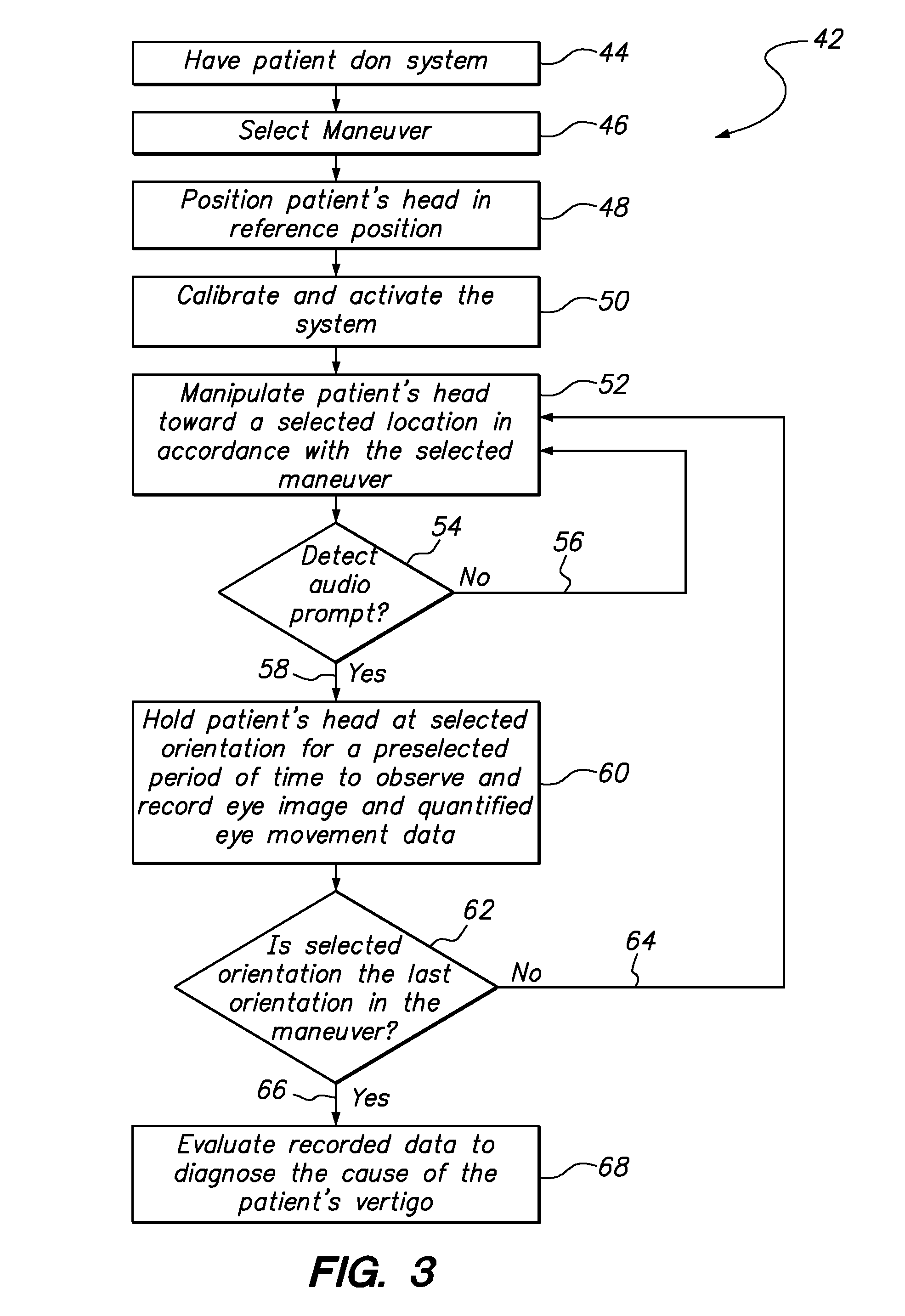
The present invention is a system for use by a clinician to diagnose balance disorders in patients. The system includes a position sensor and an optical sensor mounted on a base member that is secured over the patient's eyes during a predetermined maneuver of the head. The position sensor provides information about the patient's head orientation at different locations during the maneuver, while the optical sensor captures images of the patient's eyes and outputs an electrical signal corresponding to the video image. A computer receives the optical sensor data and performs an eyetracker analysis to identify the position of the eye in the video image and quantify the eye movement data. The computer also generates a display on the base member that shows a magnified view of the patient's eye(s) and the quantified eye movement data in real-time. The system can also include a speaker to provide audio prompts for guiding the clinician during the maneuver. The data collected from the system can be reviewed and analyzed to diagnose the cause of the patient's vertigo.

Problems solved by technology

Once the calcium crystals have been somehow repositioned, certain movements of the person's head can cause fluid in the inner ear to undergo an abnormal displacement, which in turn, results in vertigo.
It can happen, however, that there may be no trained clinician on-staff at the time a patient is admitted to the ER.

Method used


Image

  • Goggles for emergency diagnosis of balance disorders
  • Goggles for emergency diagnosis of balance disorders
  • Goggles for emergency diagnosis of balance disorders

Examples


Embodiment Construction

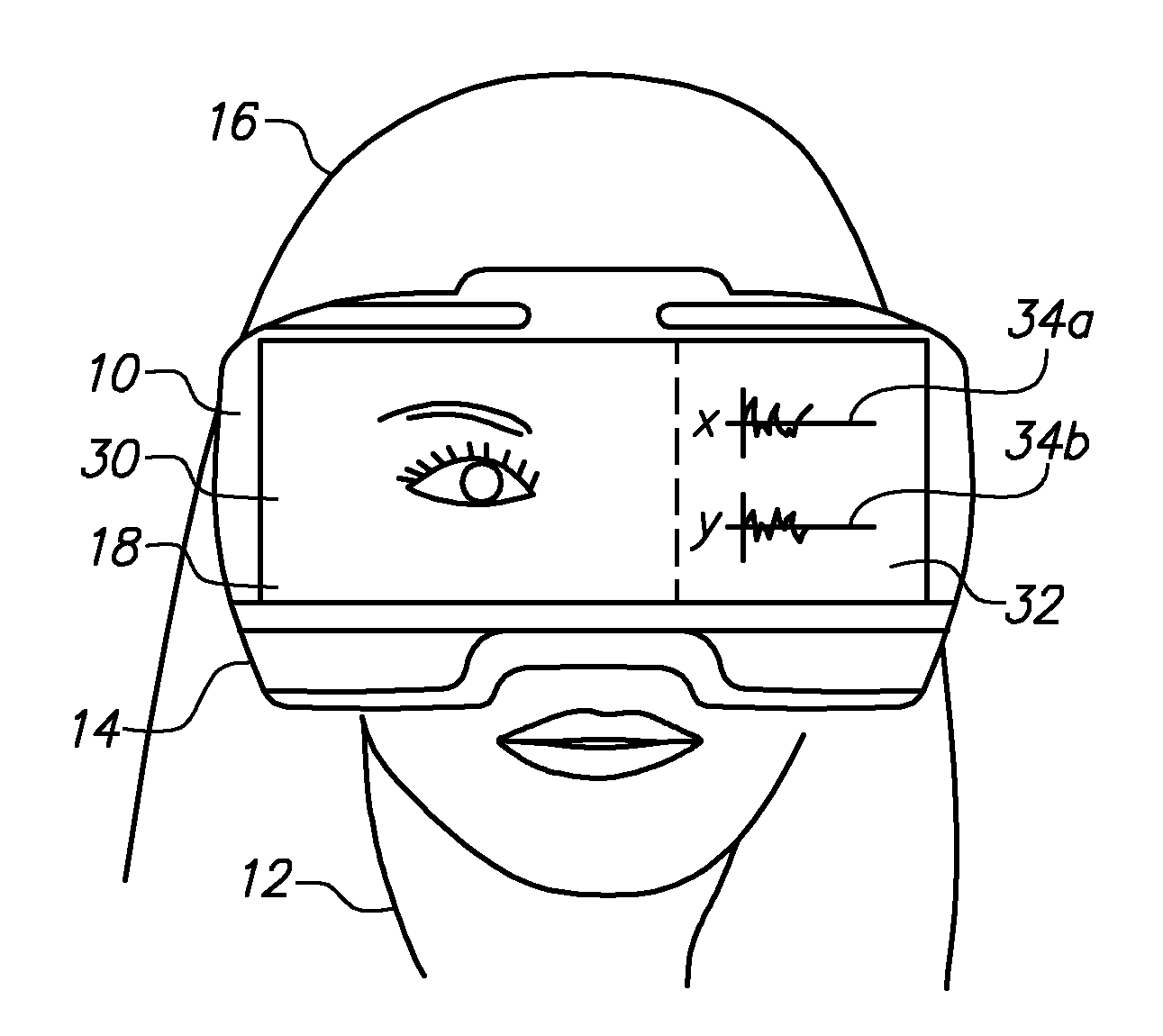
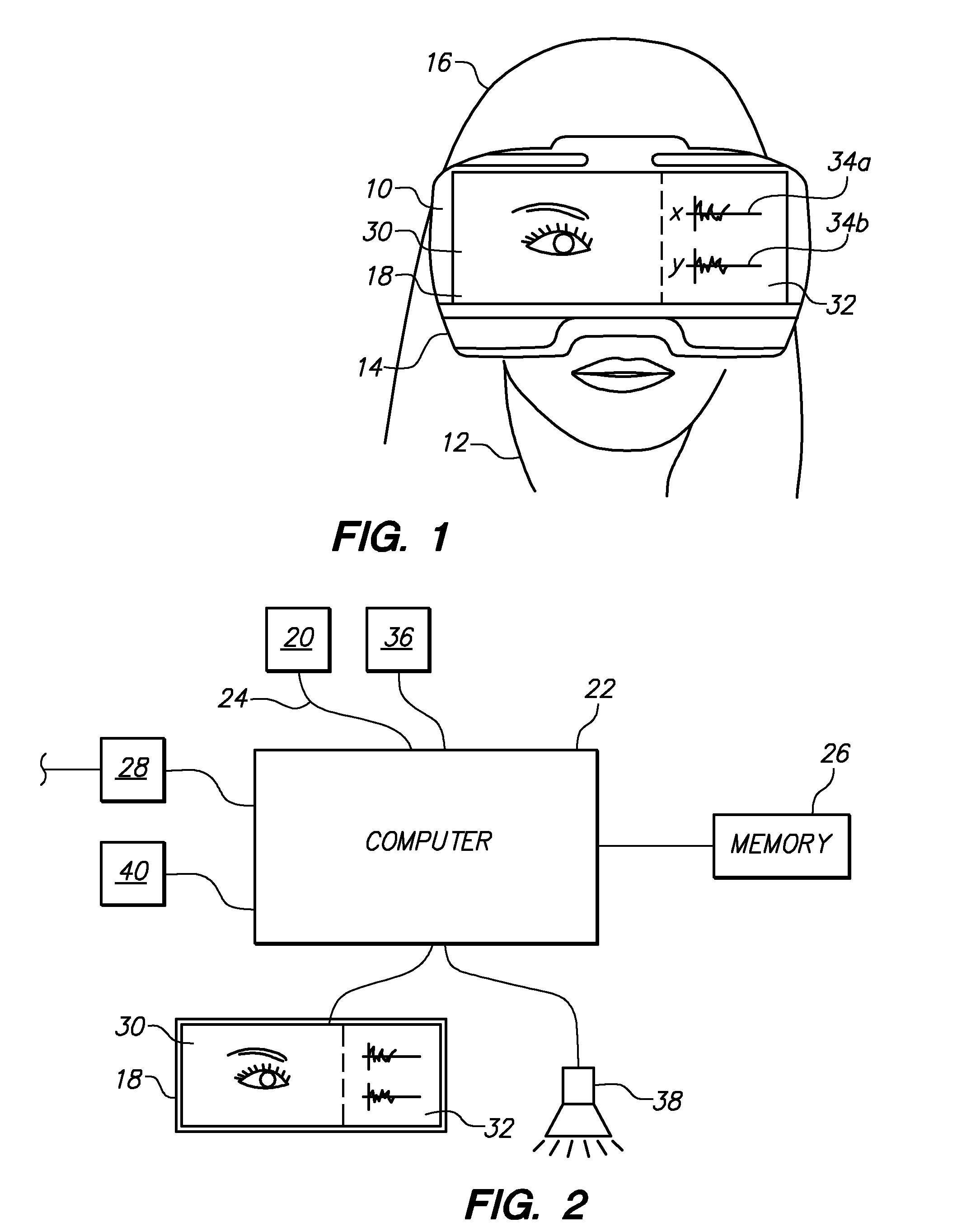
[0019]With initial reference to FIG. 1, a system 10 for use by a clinician to perform an emergency diagnosis of a patient 12 for a balance disorder is shown. As shown, the system 10 includes a base member in the form of a set of goggles 14 that are fixedly held over the eyes of the patient 12 during a predetermined maneuver of the head 16 of the patient 12. FIG. 1 also shows that a visual display 18, which may be, for example, an LCD or LED screen, is mounted on the goggles 14 and is oriented to allow a clinician (not shown) to observe the display 18 during a maneuver (described in greater detail below).

[0020]FIG. 2 shows other components of the system 10 that can be mounted on the goggles 14 shown in FIG. 1. These components include an optical sensor 20 that is positioned on a surface of the goggles 14 opposite the display 18 such that the optical sensor 20 can image one or both of the eyes of the patient 12 when the goggles 14 are secured on the patient's head 16. For example, the...


PUM


Abstract

A system for use by a clinician to perform an emergency diagnosis of a patient for a balance disorder includes a position sensor and an optical sensor that are mounted on a base member. The base member is configured to be fixedly held over the eyes of the patient during a predetermined diagnostic maneuver of the head of the patient. A processor having electronic memory is included which receives outputs from the optical sensor and the position sensor. A set of instructions constituting an eyetracker computer program is processed by the computer. Quantified eye movement data and a video stream signal can be displayed on a visual display that is affixed to the base member for observation by the clinician and recorded in computer readable memory.

Description

FIELD OF THE INVENTION[0001]The present invention pertains generally to the diagnosis of balance disorders. More particularly, the present invention pertains to systems and methods for diagnosing positional vertigo by observing a patient's eyes during a diagnostic maneuvering of the patient's head. The present invention is particularly, but not exclusively, useful as a system that can be used by a clinician to perform an emergency diagnosis of a patient for a balance disorder.BACKGROUND OF THE INVENTION[0002]Vertigo is a common medical condition in which a person temporarily experiences dizziness, a perceived spinning motion, and / or a general feeling of imbalance that can cause difficulty in standing or walking. Patients often seek medical attention after experiencing vertigo, with many of these patients choosing to find immediate treatment in an emergency room setting.[0003]Although vertigo symptoms can result from several different causes, including certain head injuries. In any e...

Claims


Application Information

Patent Timeline
IPC IPC(8): A61B3/00A61B5/11A61B5/00A61B3/14A61B3/113
CPCA61B5/4023A61B5/1112A61B3/113A61B5/7405A61B5/6803A61B3/0041A61B3/14A61B3/145A61B5/1114
Inventor QU, YINHONGPURCELL, IAN
Owner QU YINHONG
Learn More