Puckering Seal for Reduced Paravalvular Leakage

a paravalvular and sealing technology, applied in the field of replacement heart valves, can solve problems such as requiring further intervention and significant leakage, and achieve the effect of reducing the risk of leakag

Active Publication Date: 2015-01-01
ST JUDE MEDICAL CARDILOGY DIV INC
View PDF5 Cites 79 Cited by
  • Summary
  • Abstract
  • Description
  • Claims
  • Application Information

AI Technical Summary

Problems solved by technology

While most PVLs are hemodynamically non-significant, significant leaks may be problematic and require further intervention.

Method used


Image

  • Puckering Seal for Reduced Paravalvular Leakage
  • Puckering Seal for Reduced Paravalvular Leakage
  • Puckering Seal for Reduced Paravalvular Leakage

Examples


Embodiment Construction

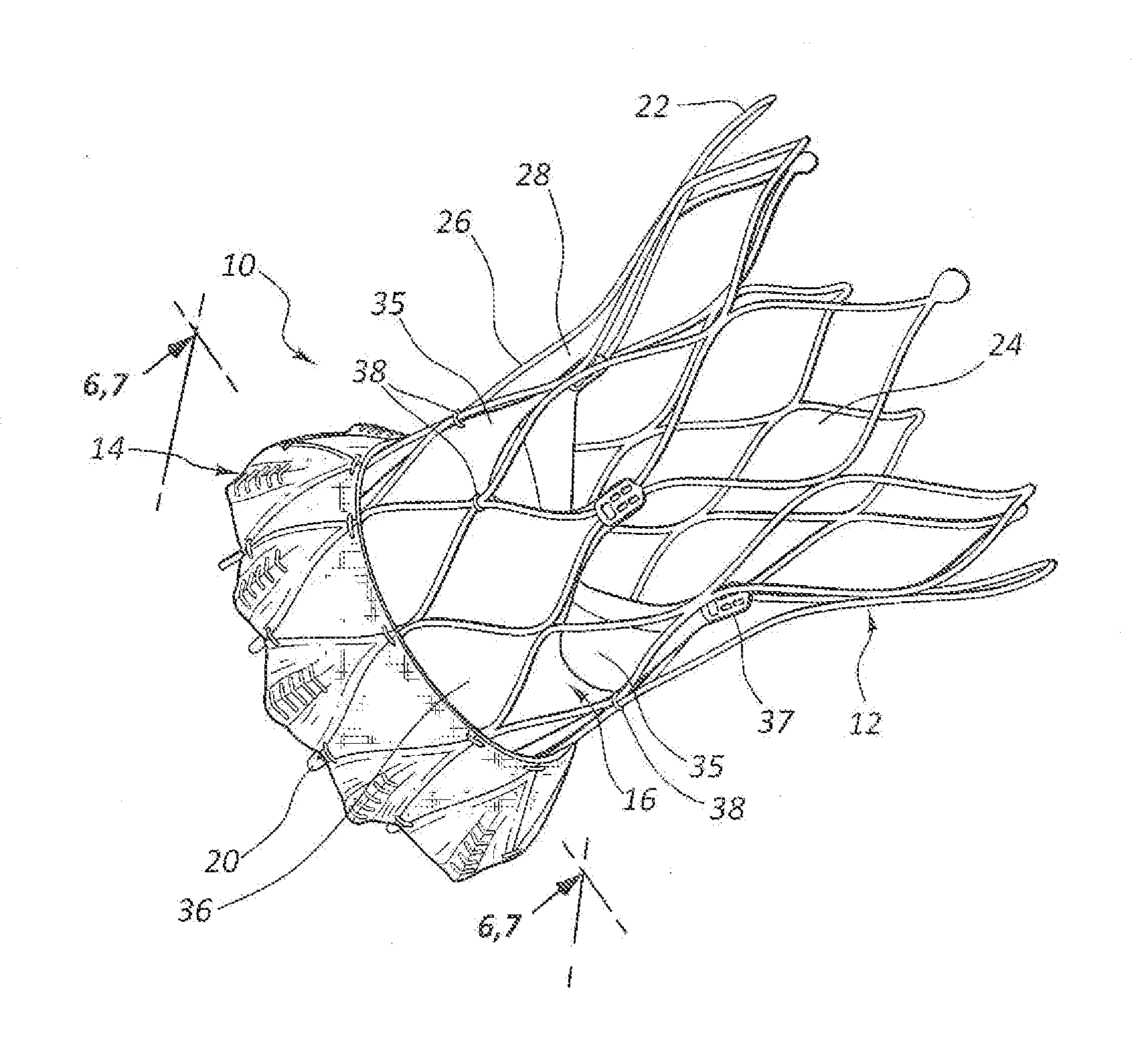
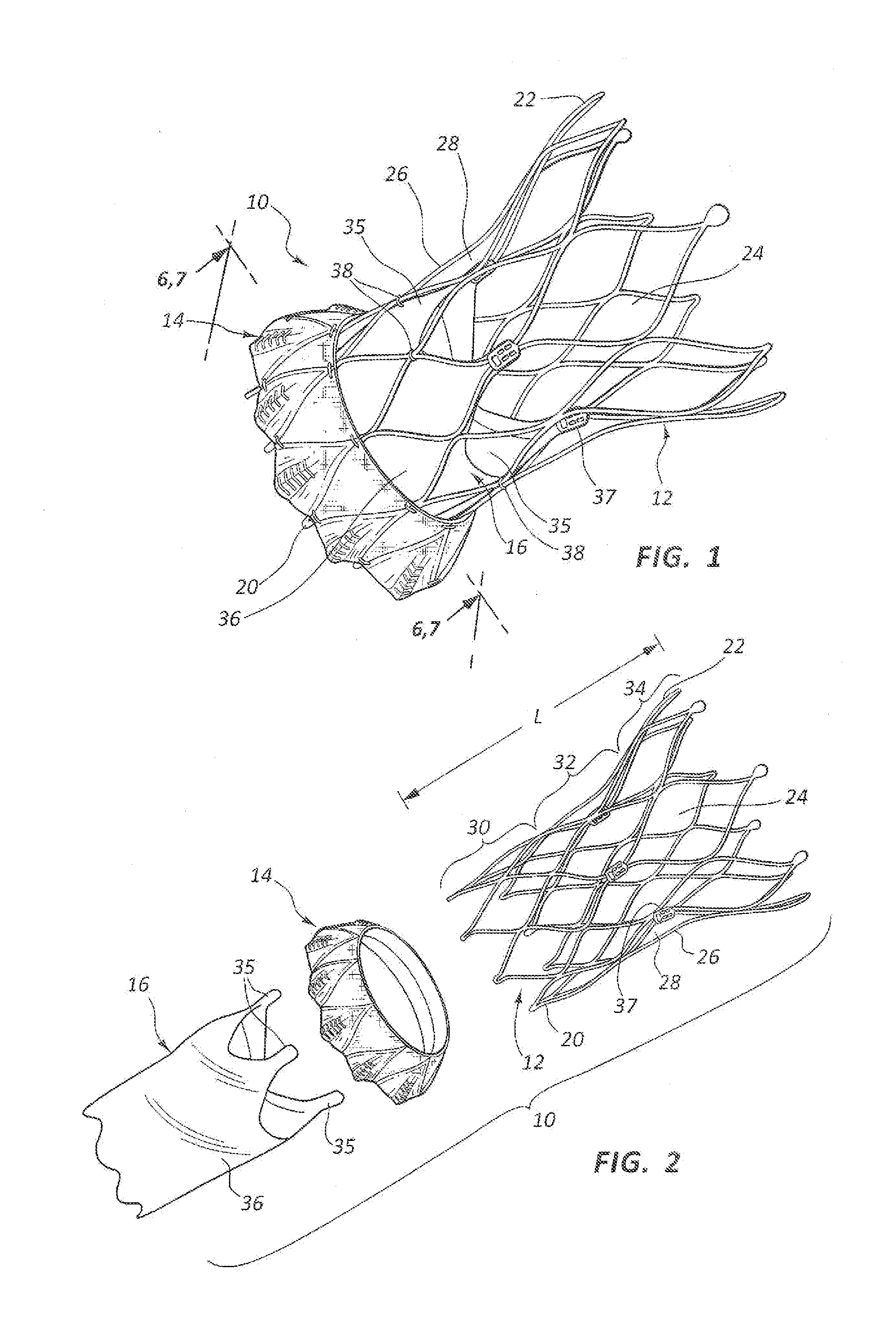
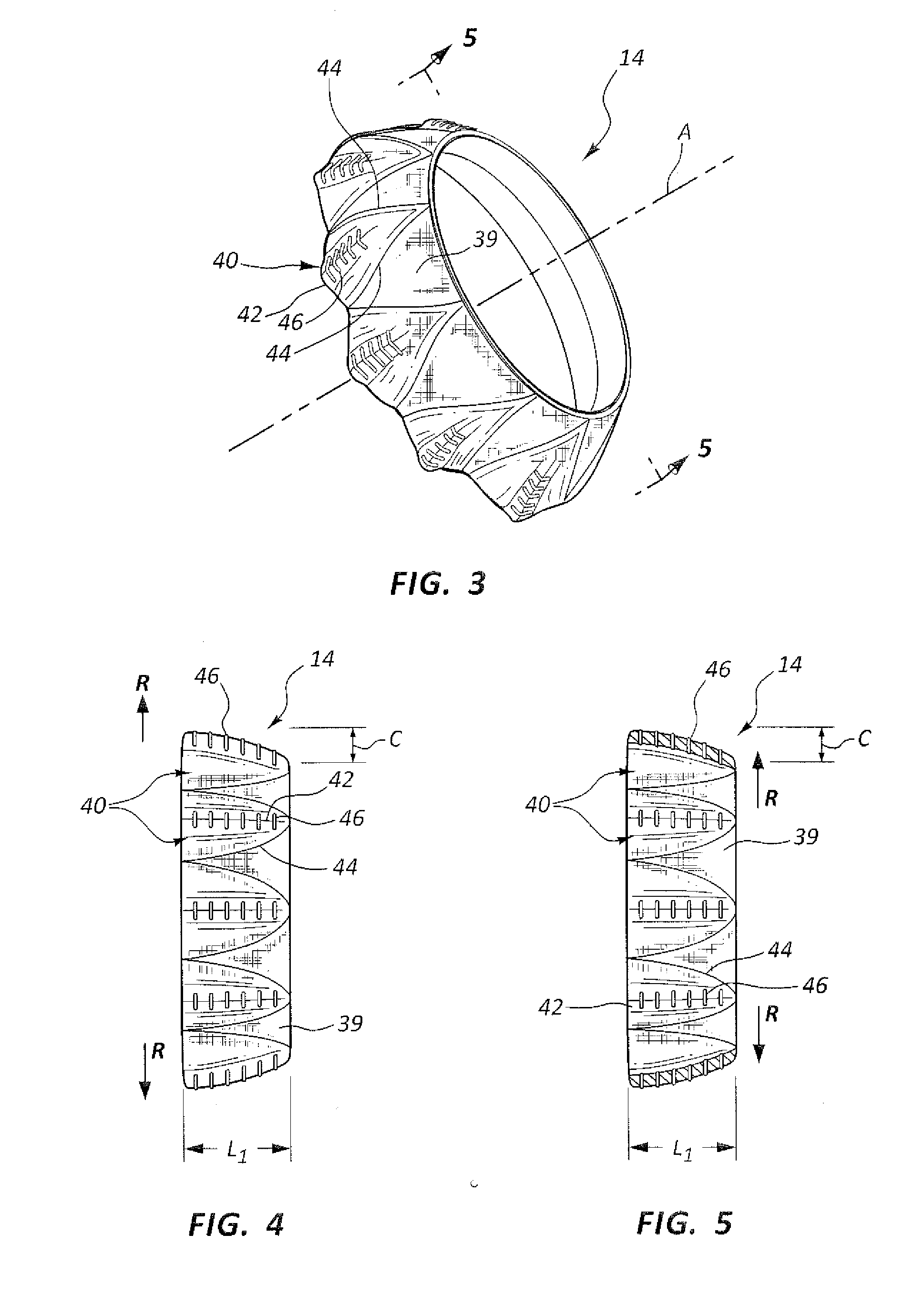
[0029]The present disclosure relates to implantable heart valve assemblies having features that address paravalvular leak (PVL). PVL involves the flow of blood around the outside of the implantable heart valve assembly between the heart valve assembly and a native annulus within which the heart valve assembly is positioned. The native annulus may include the annulus of a native heart valve, which is being replaced by the implantable heart valve assembly. PVL typically occurs when the heart valve assembly is initially placed at the native annulus and insufficient time has elapsed for tissue in-growth through the stent of the heart valve assembly, which usually mitigates PVL. One object of the present disclosure is to create a seal between an exterior of the heart valve assembly and the native valve annulus upon implantation.

[0030]One aspect of the present disclosure relates to systems and methods for providing a sealing interface between the heart valve assembly and the native annulu...


PUM

PropertyMeasurementUnit
distanceaaaaaaaaaa
distanceaaaaaaaaaa
circumferenceaaaaaaaaaa

Abstract

A heart valve assembly includes a heart valve, a self-expandable and collapsible stent, and a sealing member. The stent includes an inflow end and an outflow end and is configured to support the heart valve internally. The sealing member is connected to and extends circumferentially around the stent. The sealing member includes a plurality of radially outward extending protrusions comprising a fold of material of the sealing member.

Description

CROSS-REFERENCES TO RELATED APPLICATIONS[0001]The present application claims the benefit of the filing date of U.S. Provisional Patent Application No. 61 / 839,760, filed Jun. 26, 2013, the disclosure of which is hereby incorporated herein by reference.TECHNICAL FIELD[0002]The present disclosure relates to replacement heart valves, and more particularly relates to collapsible heart valves and associated sealing devices and methods.BACKGROUND OF THE INVENTION[0003]Prosthetic heart valves may be formed from biological materials such as harvested bovine valves or pericardial tissue. These valves are typically fitted within a stent, which may be inserted into the heart at the annulus of the compromised native valve to replace the native valve. To perform an insertion procedure using a minimally invasive transcatheter technique, it may be necessary to compress the stent to a reduced diameter for loading into a delivery device.[0004]Paravalvular (or perivalvular) leak (PVL) is a relatively ...

Claims


Application Information

Patent Timeline
Patent Type & Authority Applications(United States)
IPC IPC(8): A61F2/24
CPCA61F2/2415A61F2/2418A61F2220/0075A61F2250/006A61F2250/0069Y10T29/49412
Inventor PARA, ANDREA, N.
Owner ST JUDE MEDICAL CARDILOGY DIV INC
Why Eureka
Try Eureka