Thermal imaging device and normative photographing method for thermal image

Active Publication Date: 2015-01-08
MISSION INFRARED ELECTRO OPTICS TECH
View PDF6 Cites 14 Cited by
  • Summary
  • Abstract
  • Description
  • Claims
  • Application Information

AI Technical Summary

Benefits of technology

[0008]This invention provides a thermal imaging device and a normative photographing method for a thermal image. According to a specified position in an infrared thermal image, a reference image with a specified dimension, reflecting specified morphological characters of a photographed object, and the infrared thermal image are displayed together. The reference image is used as a visual reference of a thermal image of a photographed object during photographing, which prov

Problems solved by technology

Since infrared imaging detection technology is applied, users mainly depend on subjective experience to photograph, and fail to grasp a correct imaging shape of the photographed object and an imaging position, dimension, and angle of a thermal image of the photographed object in an infrared thermal image.
Thus, key parts during photographing may be missed, and thermal images of the same or similar photographed objects which are photographed and record each time have differences in an imaging position, an imaging dimension, or an imaging angle.
The complexity of the record thermal images of the photographed objects causes that batch processing of a computer is difficulty and the subsequent analysis needs to be finished artificially (such as setting analyzed

Method used


Image

  • Thermal imaging device and normative photographing method for thermal image
  • Thermal imaging device and normative photographing method for thermal image
  • Thermal imaging device and normative photographing method for thermal image

Examples


second embodiment

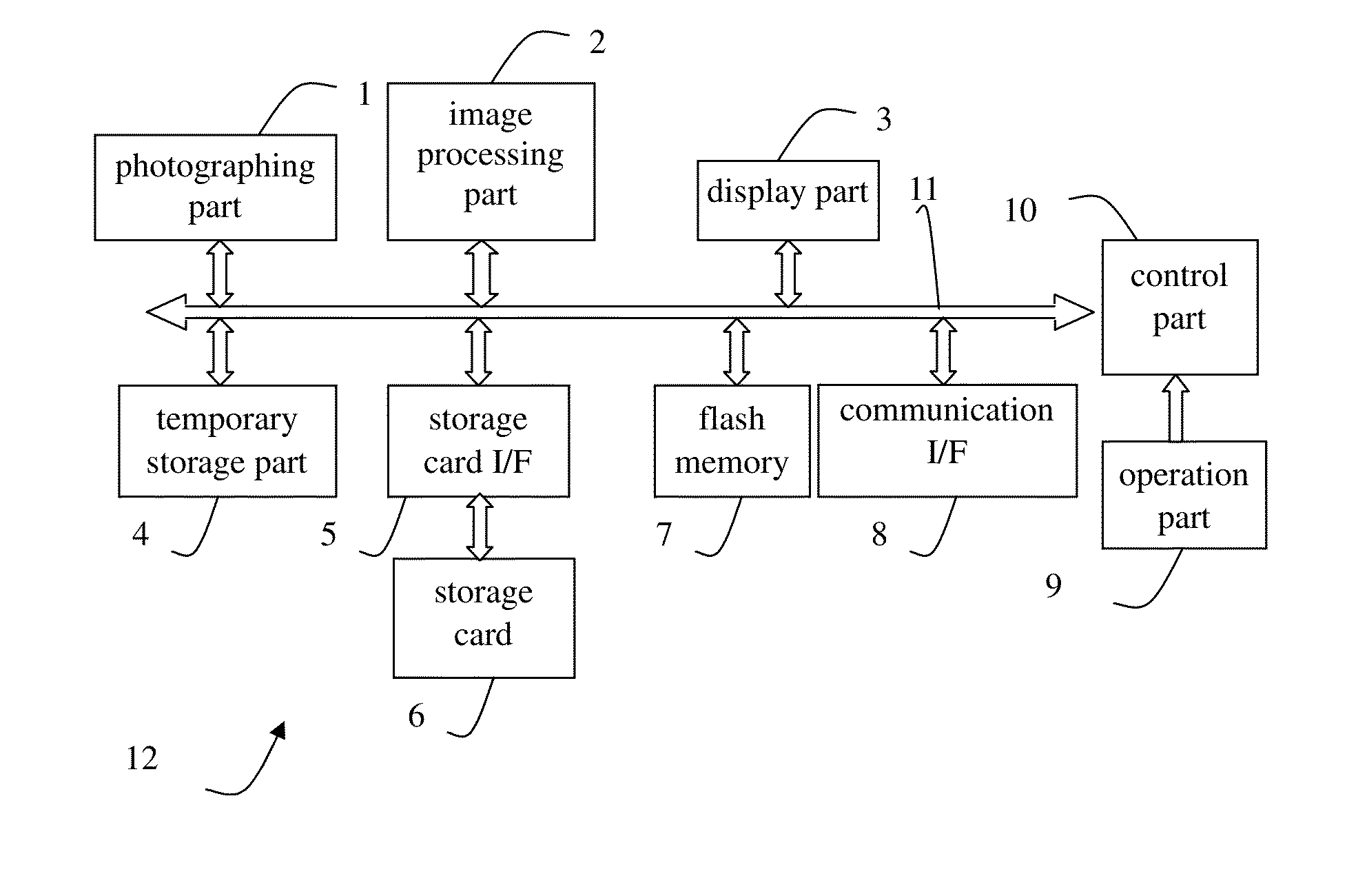
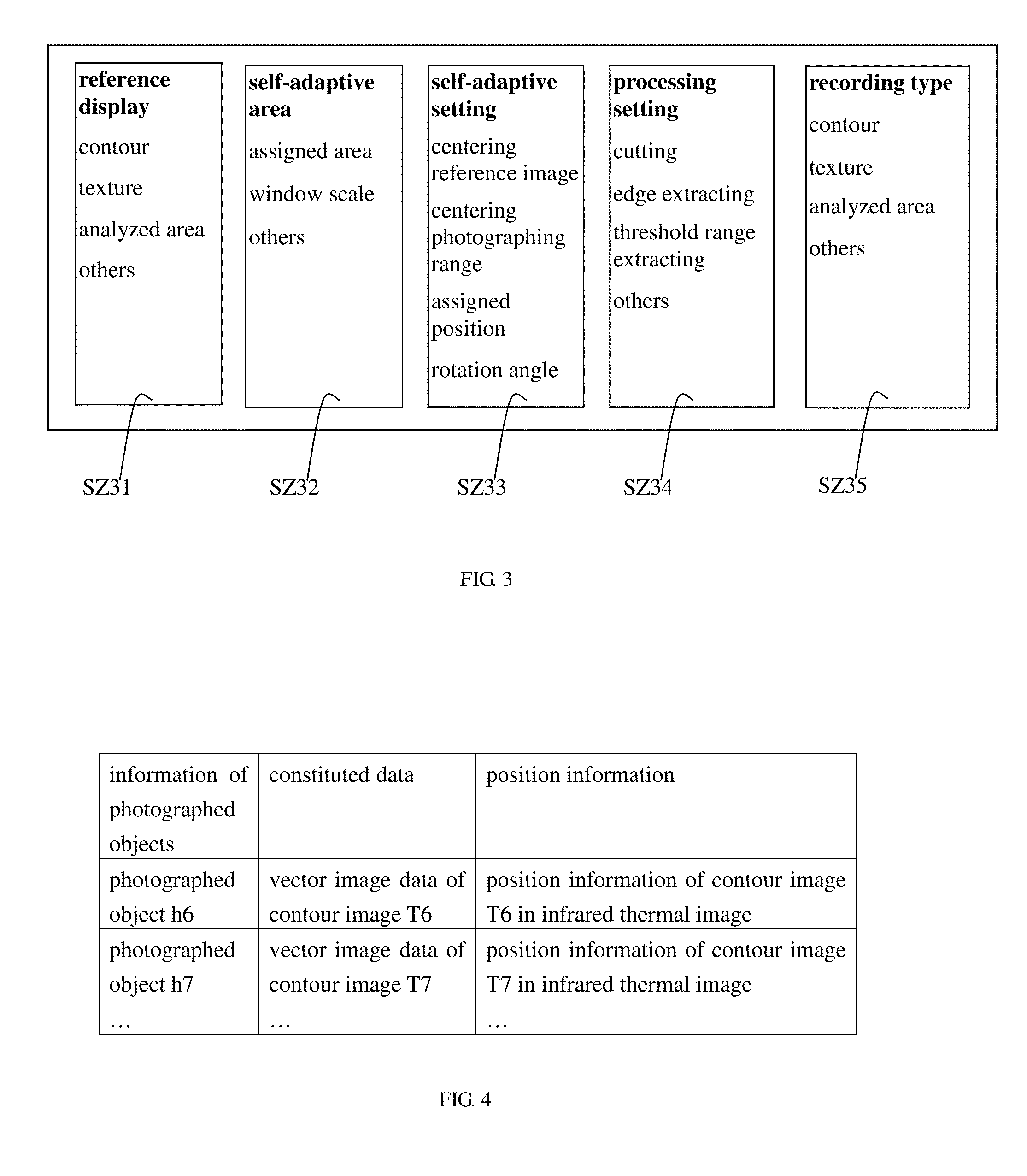
[0096]The control part 10 determines the specified position and the specified dimension of the contour image T7 located in the infrared thermal image according to the position information transmitted to the temporary storage part 4. For example, in FIG. 4, the flash memory 7 stores the morphological constituted data and the position information thereof. The position information represents the specified position and the specified dimension of the reference image generated by the morphological constituted data and located in the infrared thermal image, and the position determining part is used for determining the specified position and the specified dimension represented by the position information as the specified position and the specified dimension of the reference image acquired by the morphological constituted data in the infrared thermal image. In addition, the position, dimension, or rotating angles of the reference image may be determined via input of the user through the oper...

first embodiment

[0156]The control part 10 as the recording part builds related record between the specified record information and the infrared data. In the embodiment, the related record between the constituted data and the position information such the position and dimension of the contour image T7 and the infrared data is built. The difference with the first embodiment is that when the position information is record, the parameter information of the self-adaptive area can be record as the position information, and the position of the contour image T7 can be reappeared according to the parameter information. Then, the reference record mode may be end, or return to the step S204 for recording again.

[0157]Further, if the analyzed area F7 and the position and dimension thereof located in the infrared thermal image are record, different from the table in FIG. 5 in the first embodiment, in the table 20 in the flash memory 7, the constituted data of the analyzed area F7 is not related to the position i...

fourth embodiment

[0169]In step S304, the morphological constituted data acquired by the processing is stored, and the morphological constituted data acquired by the cutting is stored in the temporary storage part 4. In the embodiment, the morphological constituted data acquired by the processing may also be stored in the storage card 6 or the flash memory 7, or the setting mode in the fourth embodiment may be entered.

[0170]In step S305, the morphological constituted data acquired by the processing is determined as the constituted data related to the reference image.

[0171]The control part 10 as the reference image determining part determines the morphological constituted data acquired by the processing and stored in the storage part (such as the temporary storage part 4) as the constituted data related to the reference image synthesized with the infrared thermal image. Step S306 is entered.

[0172]In step S306, the specified position and the specified dimension of the reference image located in the inf...


PUM


Abstract

This invention provides a thermal imaging device and a normative photographing method for a thermal image. In the prior art, when the thermal imaging device is used, a photographing part, angle, and distance of a photographed object are selected according to subjective experience of users, thus lowering photographing speeds and having omissions, and a position, dimension, and angle of thermal images of similar photographed objects in infrared thermal images photographed each time are different, causing subsequent analysis trouble. In this invention, via a reference image with a specified position and dimension presented in the infrared thermal image and reflecting specified morphological characters of the photographed object, a visual reference of predetermined thermal image quality and photographing requirements of the photographing object is provided, assisting the users to correctly grasp imaging states and photographing distances of the thermal image, thereby acquiring uniform normative thermal image of the photographed object.

Description

BACKGROUND OF THE INVENTION[0001]1. Field of the Invention[0002]This invention relates to a thermal imaging device and an infrared detection filed and, more particularly, to a thermal imaging device and a normative photographing method for a thermal image.[0003]2. Description of the Related Art[0004]As prior art, a thermal imaging device for imaging by receiving external infrared radiation energy is widely used. During photographing, each photographed object has specific requirements of a photographing part and a photographing angle, thereby presenting a specific imaging shape. Since infrared imaging detection technology is applied, users mainly depend on subjective experience to photograph, and fail to grasp a correct imaging shape of the photographed object and an imaging position, dimension, and angle of a thermal image of the photographed object in an infrared thermal image. Thus, key parts during photographing may be missed, and thermal images of the same or similar photographe...

Claims


Application Information

Patent Timeline
IPC IPC(8): H04N5/33H04N5/232
CPCH04N5/33H04N5/23293H04N5/23229G01J2005/0077H04N23/64H04N23/635H04N23/80
Inventor WANG, HAO
Owner MISSION INFRARED ELECTRO OPTICS TECH
Why Eureka
Try Eureka