Imaging device and imaging method

a technology of imaging device and image quality, which is applied in the direction of instruments, television systems, color signal processing circuits, etc., can solve the problems of degrading the image quality of the images corresponding to the respective focal lengths, not fully utilizing the focal length and the focal distance, and not achieving the effect of accurate removal, favorable image quality and favorable image quality

Active Publication Date: 2015-01-08
FUJIFILM CORP
View PDF5 Cites 17 Cited by
  • Summary
  • Abstract
  • Description
  • Claims
  • Application Information

AI Technical Summary

Benefits of technology

[0025]In an imaging device according to a second mode of the present invention, in the first mode, the image correcting unit performs the removal in consideration of position dependency of a degree of the influence of the light beam passing through the region other than the one region in the generated image. This refers to that dependency of the degree of mixture of the above-described crosstalk components also on the location in the image is taken into consideration. With this, in the imaging device according to the second mode, the crosstalk components can be accurately removed, and images with more favorable image quality can be obtained.
[0026]In an imaging device according to a third mode of the present invention, in the second mode, the image correcting unit removes an influence of shading on the light beam passing through the one region from the image generated so as to correspond to the one region. In the imaging device according to the third mode, the influence of not only crosstalk in the target region from another region but also shading (shading with respect to main gain) of the light beam itself passing through the one region is removed. With this, images with more favorable image quality can be obtained.
[0027]In an imaging device according to a fourth mode of the present invention, in any of the first to third modes, the image correcting unit performs the removal in consideration of position dependency of the degree of the influence of shading in the generated image. In the fourth mode, as with the case of crosstalk, this refers to that the influence of shading depends also on the location in the image is taken into consideration. With this, the influence of shading can be accurately removed, and images with more favorable image quality can be obtained.

Problems solved by technology

However, in these conventional techniques, image quality of the images corresponding to the respective focal lengths is not favorable, and the features of the lens with many characteristics (such as the focal length and the focal distance) are not fully utilized.
For example, the technique described in the above-described PTL 1 has a problem in which, since signals corresponding to a plurality of focal lengths are superposed on an output from an image sensor, the influence of signals corresponding to different focal lengths is not fully separated, thereby degrading image quality of the images corresponding to the respective focal lengths.
Also, in a mode in which a shape-variable iris letting subject light passing through only any of focal regions is arranged near the lens and only an image corresponding to any relevant focal length is obtained, there is a problem, for example, in which a plurality of images corresponding to a plurality of focal length cannot be simultaneously obtained.
Moreover, to avoid degradation in image quality as described above, if imaging is performed a plurality of times by changing the focal length of the taking lens, imaging takes time.
Furthermore, problems may occur such that the subject moves or the brightness of the subject changes during imaging to vary imaging conditions among images.

Method used


Image

  • Imaging device and imaging method
  • Imaging device and imaging method
  • Imaging device and imaging method

Examples


Embodiment Construction

[0056]Modes for carrying out the imaging device and imaging method according to the present invention are described in detail below by following the attached drawings.

[0057]

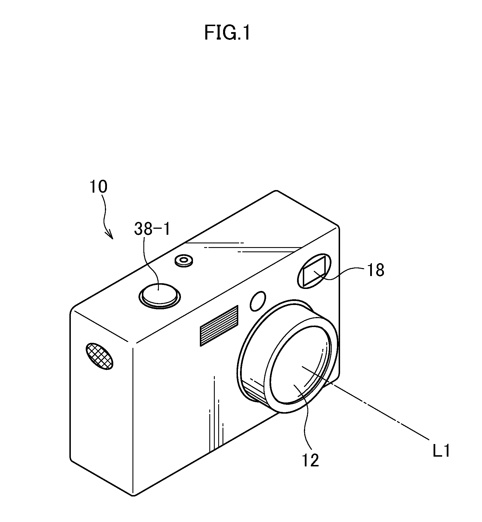
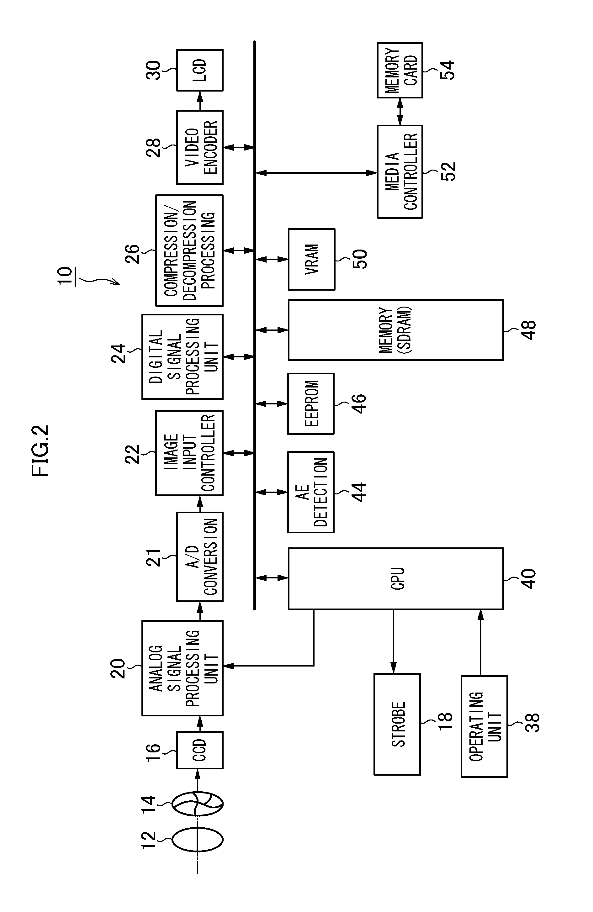
[0058]FIG. 1 is an external perspective view of an imaging device 10 (imaging device) according to a first embodiment. FIG. 2 is a block diagram depicting the structure of main parts of the imaging device 10. As depicted in FIG. 1, a taking lens 12 (taking lens), a strobe 18, and so on are arranged on the front surface of the imaging device 10, and a release button 38-1 is provided on the upper surface. L1 represents an optical axis of the taking lens 12.

[0059]FIG. 2 is a block diagram depicting the structure of main parts of the imaging device 10. The operation of the imaging device 10 as a while is controlled by a central processing device (CPU) 40 in a centralized manner, and programs required for the operation of the CPU 40 (including programs for use in imaging processing, image generation / combining processi...


PUM


Abstract

In an imaging method according to the present invention, in an imaging device including a taking lens having a plurality of regions each with an independent characteristic and an image pickup element having a plurality of light-receiving sensors provided so as to correspond to the plurality or regions, the plurality of light-receiving sensors performing pupil division of a light beam passing through any of the plurality of regions for selective light-receiving, from an imaging signal from a light-receiving sensor corresponding to one region of the plurality of regions, an image corresponding to the one region is generated. When the generated image is corrected, an influence of a light beam passing through a region other than the one region is removed from the image generated so as to correspond to the one region.

Description

CROSS-REFERENCE TO RELATED APPLICATIONS[0001]This application is a Continuation of PCT International Application No. PCT / JP2013 / 057989 filed on Mar. 21, 2013, which claims priority under 35 U.S.C. §119(a) to Japanese Patent Application No. 2012-71123 filed on Mar. 27, 2012. Each of the above application(s) is hereby expressly incorporated by reference, in its entirety, into the present application.BACKGROUND OF THE INVENTION[0002]1. Field of the Invention[0003]The present invention relates to an imaging device and imaging method capable of obtaining a plurality of images with different characteristics.[0004]2. Description of the Related Art[0005]In the field of imaging devices, a technique has been known in which a plurality of images with different characteristics are obtained by imaging a plurality of times with varied imaging conditions or using lens systems having a plurality of characteristics and the obtained images are processed according to the purpose (for example, refer to...

Claims


Application Information

Patent Timeline
Patent Type & Authority Applications(United States)
IPC IPC(8): H04N5/359H04N5/243
CPCH04N5/243H04N5/3595H04N23/81H04N23/55H04N23/67H04N23/80H04N23/631H04N23/743H04N25/702H04N25/625H04N23/76G03B15/00
Inventor ONO, SHUJI
Owner FUJIFILM CORP
Why Eureka
Try Eureka