
Display apparatus, automotive display apparatus, and method for manufacturing the display apparatus

Active Publication Date: 2015-01-08
NISSAN MOTOR CO LTD
View PDF2 Cites 12 Cited by
  • Summary
  • Abstract
  • Description
  • Claims
  • Application Information

AI Technical Summary

Benefits of technology

The present invention aims to improve the visibility of displayed images by enhancing their polarization properties. Specifically, it provides a display apparatus, an automotive display apparatus, and a method for manufacturing the display apparatus that can enhance polarization solving for displayed images.

Problems solved by technology

However, a size of the porous particles described in Patent Literature 1 is a few micrometers in diameter at minimum, and a haze (opacity) of the polarization solving plate is increased by the fact that the porous particles become a diffusion source of incident visible light, whereby the polarization solving plate becomes unsuitable for a display apparatus for which high transparency is required.

Method used


Image

  • Display apparatus, automotive display apparatus, and method for manufacturing the display apparatus
  • Display apparatus, automotive display apparatus, and method for manufacturing the display apparatus
  • Display apparatus, automotive display apparatus, and method for manufacturing the display apparatus

Examples


example 1

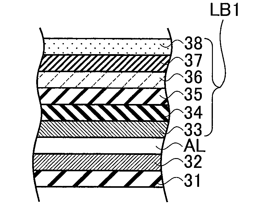
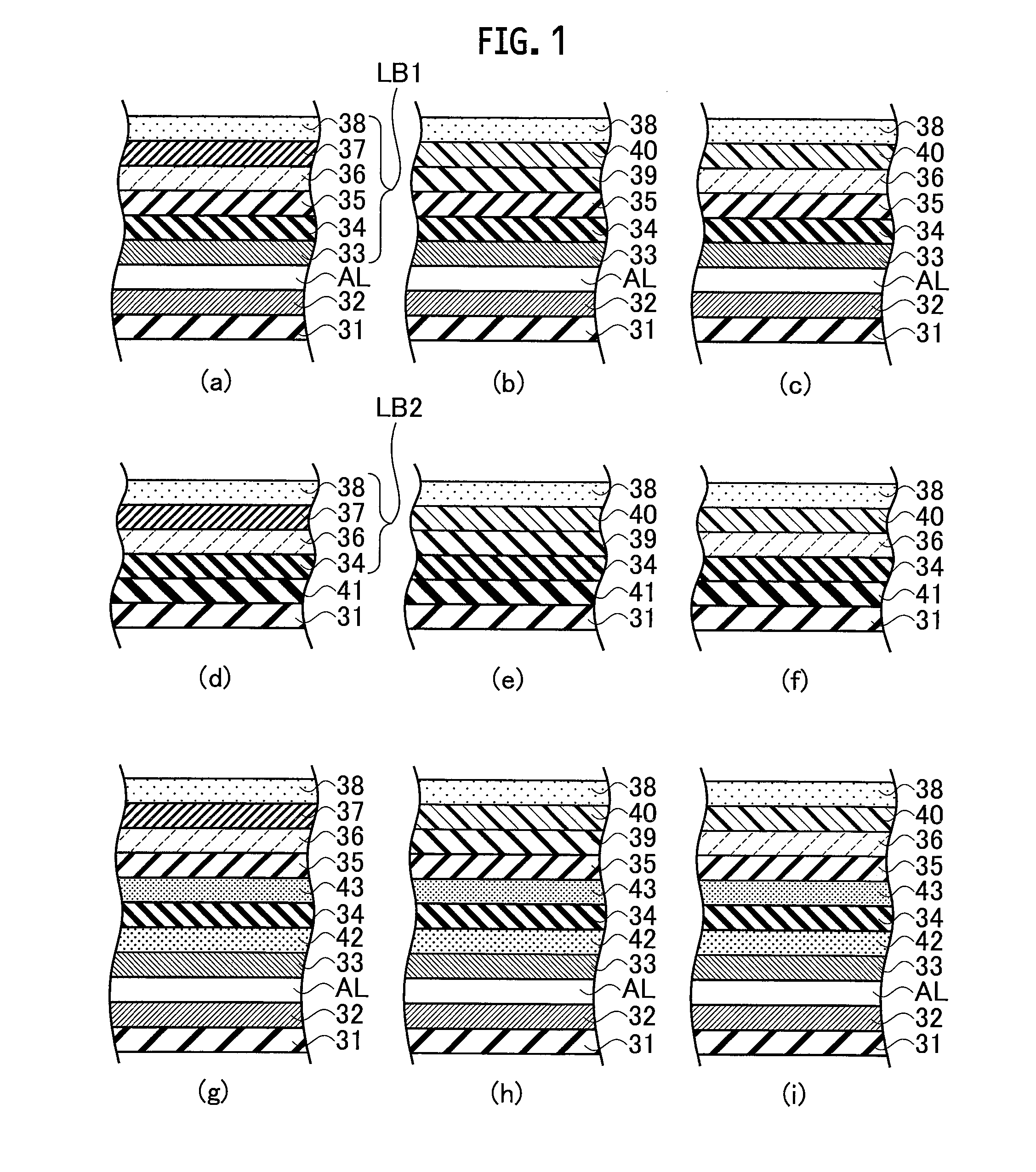
[0056]FIG. 1A shows a cross-sectional configuration of the display apparatus according to Example 1. The liquid crystal panel 31 has a configuration shown in FIG. 3, and above the output side of the liquid crystal panel 31, the touch panel 34 of the electrostatic capacitance type is arranged while interposing the gas layer AL therebetween. Onto the interface between the liquid crystal panel 31 and the gas layer AL, and onto the interface between the touch panel 34 and the gas layer AL, the AR films 32 and 33 are pasted, respectively. In such a way, the reflection of light on the interface between the liquid crystal panel 31 and the gas layer AL and on the interface between the touch panel 34 and the gas layer AL is suppressed.

[0057]On the touch panel 34, the linear polarization layer 35 is stacked. Above the linear polarization layer 35, the base material layer 37 is stacked while interposing the adhesive layer 36 therebetween. In Example 1, the adhesive layer 36 is composed of the ...

example 2

[0059]FIG. 1B shows a cross-sectional configuration of the display apparatus according to Example 2. In Example 2, the adhesive layer 39 is composed of the acrylic adhesive that does not contain the polarization solving fiber, and the base material layer 40 is made of the polarization solving base material that contains the polarization solving fiber. Other points are the same as those of FIG. 1A, and a description thereof is omitted.

example 3

[0060]FIG. 1C shows a cross-sectional configuration of the display apparatus according to Example 3. In Example 3, the adhesive layer 36 is composed of the polarization solving adhesive containing the polarization solving fiber, and the base material layer 40 is composed of the polarization solving base material containing the polarization solving fiber. That is to say, both of the base material layer 40 and the adhesive layer 36 contain the polarization solving fiber. Other points are the same as those of FIG. 1A, and a description thereof is omitted.


PUM


Abstract

A display apparatus includes: a liquid crystal panel (31); a touch panel (31) placed on the liquid crystal panel (31); a base material layer (37, 40) stacked on the touch panel (34); and an adhesive layer (36, 39) interposed between the touch panel (34) and the base material layer (37, 40). Fiber having properties to solve polarization is contained in at least one of the base material layer (37, 40) and the adhesive layer (36, 39).

Description

TECHNICAL FIELD[0001]The present invention relates to a display apparatus including a liquid crystal panel, to an automotive display apparatus, and to a method for manufacturing the display apparatus.BACKGROUND ART[0002]A liquid crystal panel has a configuration, in which liquid crystal is filled into a gap between two glass plates, and a polarization plate is arranged on an outside of one of the glass plates, and accordingly, a displayed image displayed on the liquid crystal panel is linearly polarized in terms of principle. In a case where the displayed image, which is linearly polarized, is observed through sunglasses having a polarization function, and a polarization direction of the sunglasses and a polarization direction of the displayed image forms a relationship of the crossed Nicols, then a quantity of light transmitting through the sunglasses is lowered to a large extent, and visibility of the displayed image is significantly lowered.[0003]As a technology for solving such ...

Claims


Application Information

Patent Timeline
IPC IPC(8): G02F1/1335G02F1/13363G02F1/1333
CPCG02F1/133528G02F1/13338G02F2001/133638G02F1/1333G02F1/13363G02F1/1335G02B5/30G09F9/00G02F2203/06G06F3/0412C09K2323/03G02F1/0139G02F1/133638G06F3/041
Inventor UNNO, HARUOYAMAMOTO, ISAO
Owner NISSAN MOTOR CO LTD
Learn More