Light source apparatus, vehicle headlamp and vehicle headlamp system

Inactive Publication Date: 2015-01-08
STANLEY ELECTRIC CO LTD
View PDF15 Cites 16 Cited by
  • Summary
  • Abstract
  • Description
  • Claims
  • Application Information

AI Technical Summary

Benefits of technology

[0008]It is therefore an object of the specific aspects according to the present invention to provide a technique capable of reducing the number o

Problems solved by technology

When driving a vehicle at night, a driver basically checks the area in front of the vehicle by irradiating a high beam from the headlamps, switching to a low beam as necessary, but also often uses the low beam due to the hassle of switching

Method used


Image

  • Light source apparatus, vehicle headlamp and vehicle headlamp system
  • Light source apparatus, vehicle headlamp and vehicle headlamp system
  • Light source apparatus, vehicle headlamp and vehicle headlamp system

Examples


Embodiment Construction

[0033]Now, an embodiment of the present invention will be described below with reference to the accompanying drawings.

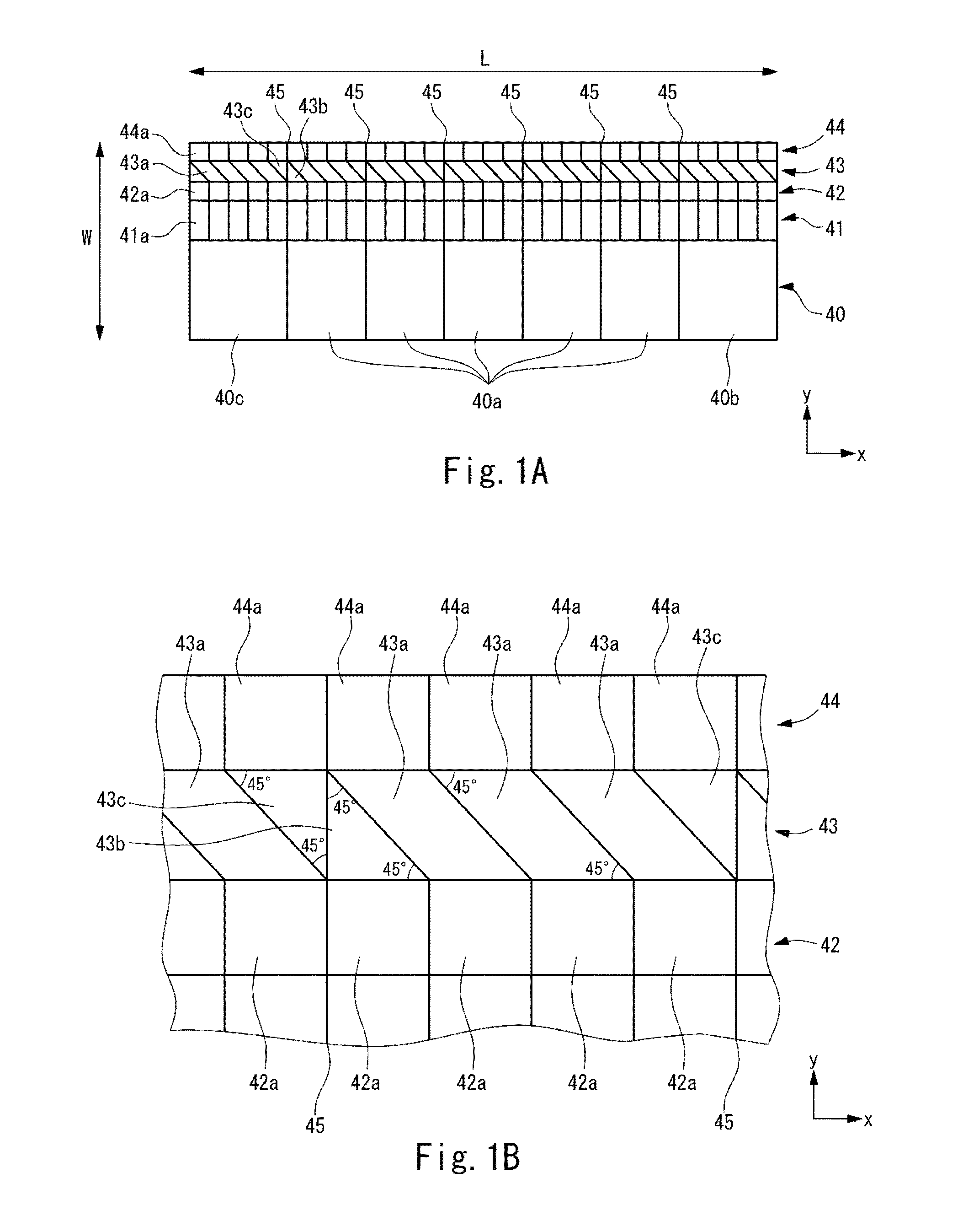
[0034]FIG. 1A is a plan view schematically showing the configuration of a matrix LED as the light source apparatus of an embodiment. The matrix LED in the figure is configured to comprise a plurality of light-emitting devices (LEDs) arranged with regularity. FIG. 1A mainly shows the shapes of the light-emitting units of the respective light-emitting devices. The matrix LED in the figure comprises a plurality of light-emitting device arrays 40, 41, 42, 43, and 44. The respective light-emitting device arrays 40 and the like each comprise a plurality of light-emitting devices arranged in a first direction (direction x in the figure). As shown in the figure, the light-emitting units (light-emitting surfaces) of the respective light-emitting devices comprise various sizes and shapes. The matrix LED is rectangular in shape overall, with a long-side length L of 9 mm and a s...


PUM


Abstract

A light source apparatus having a plurality of light-emitting device arrays, each extending in a first direction and adjacently disposed in a second direction that crosses the first direction is disclosed. Each of the plurality of light-emitting device arrays comprises a plurality of light-emitting devices arranged along the first direction and is the same in length. Among the plurality of light-emitting device arrays, the number of the respective light-emitting devices of a first light-emitting device array at one end in a second direction is smaller than the number of the respective light-emitting devices of a second light-emitting device array adjacent to the first light-emitting device array. The surface area of the light-emitting units of the respective light-emitting devices of the first light-emitting device array is larger than that of the light-emitting units of the respective light-emitting devices of the second light-emitting device array adjacent to the first light-emitting device array.

Description

BACKGROUND OF THE INVENTION[0001]1. Field of the Invention[0002]The present invention relates to a light distribution control technique that controls a light irradiation range per subsection when light is irradiated in front of a vehicle.[0003]2. Description of the Background Art[0004]When driving a vehicle at night, a driver basically checks the area in front of the vehicle by irradiating a high beam from the headlamps, switching to a low beam as necessary, but also often uses the low beam due to the hassle of switching as well as the road environment. Hence, light is irradiated on the upper side above a so-called cutoff line, possibly casting glare onto an oncoming vehicle or preceding vehicle (hereinafter referred to as “forward vehicle”). Thus, as disclosed in Japanese Patent No. 4624257 for example, in recent years there have been proposed various light distribution control techniques for detecting the position of the lamps (tail lamps or headlamps) of the forward vehicle using...

Claims


Application Information

Patent Timeline
IPC IPC(8): B60Q1/08F21K99/00F21S8/10
CPCB60Q1/08F21S48/115F21S48/1705F21K9/58F21S48/1291B60Q1/143B60Q2300/41B60Q2300/112B60Q2300/122B60Q2300/42B60Q2300/056F21S41/192F21S41/143F21S41/663F21S41/151
Inventor SEKIGUCHI, TATSUYAKAIZUMI, YASUAKIMATSUZAKI, MAKIO
Owner STANLEY ELECTRIC CO LTD
Why Eureka
Try Eureka