Multi- fiber, fiber optic cable assemblies providing constrained optical fibers within an optical fiber sub-unit, and related fiber optic components, cables, and methods

a fiber optic cable and fiber optic sub-unit technology, applied in the field of fiber optic cables, can solve the problems of fiber distribution cables in fiber optic communications networks, transmission errors, and damage to optical fibers in multi-fiber distribution cables, and achieve the effects of reducing the complexity of fiber optic cable assembly preparation, and reducing the risk of damag

Active Publication Date: 2015-01-08
CORNING OPTICAL COMM LLC
View PDF3 Cites 3 Cited by
  • Summary
  • Abstract
  • Description
  • Claims
  • Application Information

AI Technical Summary

Benefits of technology

[0007]Embodiments disclosed in the detailed description include multi-fiber, fiber optic cables providing constrained optical fibers within an optical fiber sub-unit disposed in a cable jacket. Related fiber optic components and fiber optic assemblies are also disclosed. In one embodiment, one or more optical fiber sub-units can be provided that each comprises a plurality of optical fibers disposed adjacent one or more sub-unit strength members within a sub-unit jacket. Movement of optical fibers within a sub-unit jacket is constrained by an interior wall of the sub-unit jacket and / or the sub-unit strength members disposed in the sub-unit jacket. In this manner as a non-limiting example, optical fibers disposed in an optical fiber sub-unit can be held together as a unit within the optical fiber sub-unit. By providing the optical fibers constrained as a unit in optical fiber sub-units, the optical fiber sub-units may be constrained in a furcation assembly without having to expose the optical fibers within the optical fiber sub-units, thereby reducing complexity in fiber optic cable assembly preparations. Avoiding exposing optical fibers in a furcation assembly may also reduce the risk of damaging the optical fibers during furcation assembly preparations. Constraining the optical fibers within the optical fiber sub-units may also, as non-limiting examples, provide low optical skew, may reduce or eliminate entanglement between the optical fibers and the cable strength members to reduce or avoid optical attenuation, and / or may allow the optical fibers to act as anti-buckling components within the fiber optic cable.
[0008]As one non-limiting option, the optical fiber sub-units may be disposed adjacent to the cable strength members within the cable jacket in a manner that allows movement between the optical fiber sub-units and the cable strength members within the cable jacket. In this manner, the one or more optical fiber sub-units can freely move within the cable jacket in this embodiment. As a result in one non-limiting example, entanglements between the cable strength member and the optical fiber sub-units that may cause optical attenuation or broken fibers may be avoided. Stranding can cause a bend to be disposed in the optical fiber sub-units thereby attenuating optical signals carried by the optical fibers in the optical fiber sub-units.
[0010]In this embodiment, the one or more cable strength members are disposed within the cable jacket in a first length, and the one or more optical fiber sub-units are disposed within the cable jacket in a second length, the second length greater than the first length. In this manner as a non-limiting example, a tensile load (e.g., a pulling load) placed on the furcation assembly is directed more to the one or more cable strength members to avoid or reduce stress placed on the optical fibers. As a non-limiting option in this embodiment, the optical fiber sub-units are disposed adjacent to the cable strength members within the cable jacket that allows movement between the one or more optical fiber sub-units and the one or more cable strength members within the cable jacket. As another non-limiting example, the optical fiber sub-units can include tight buffered optical fibers that are disposed adjacent to strength members disposed within the sub-unit jackets, wherein movement between is allowed between the optical fiber sub-units and the one or more cable strength members within the cable jacket of the fiber optic cable.

Problems solved by technology

Use of multi-fiber distribution cables in a fiber optic communications network can present certain challenges.
For example, excessive optical skew or delay can cause transmission errors.
Optical fibers in multi-fiber distribution cables can be damaged if the cable is subject to excessive bending.
However, the optical fibers may engage and become entangled with the strength members thereby bending the optical fibers inside the cable jacket and attenuating the optical signals carried on the optical fibers.
Transferring excessive load to optical fibers disposed in a fiber optic cable can damage the optical fibers.

Method used


Image

  • Multi- fiber, fiber optic cable assemblies providing constrained optical fibers within an optical fiber sub-unit, and related fiber optic components, cables,  and methods
  • Multi- fiber, fiber optic cable assemblies providing constrained optical fibers within an optical fiber sub-unit, and related fiber optic components, cables,  and methods
  • Multi- fiber, fiber optic cable assemblies providing constrained optical fibers within an optical fiber sub-unit, and related fiber optic components, cables,  and methods

Examples


Embodiment Construction

[0032]Reference will now be made in detail to the embodiments, examples of which are illustrated in the accompanying drawings, in which some, but not all embodiments are shown. Indeed, the concepts may be embodied in many different forms and should not be construed as limiting herein; rather, these embodiments are provided so that this disclosure will satisfy applicable legal requirements. Whenever possible, like reference numbers will be used to refer to like components or parts.

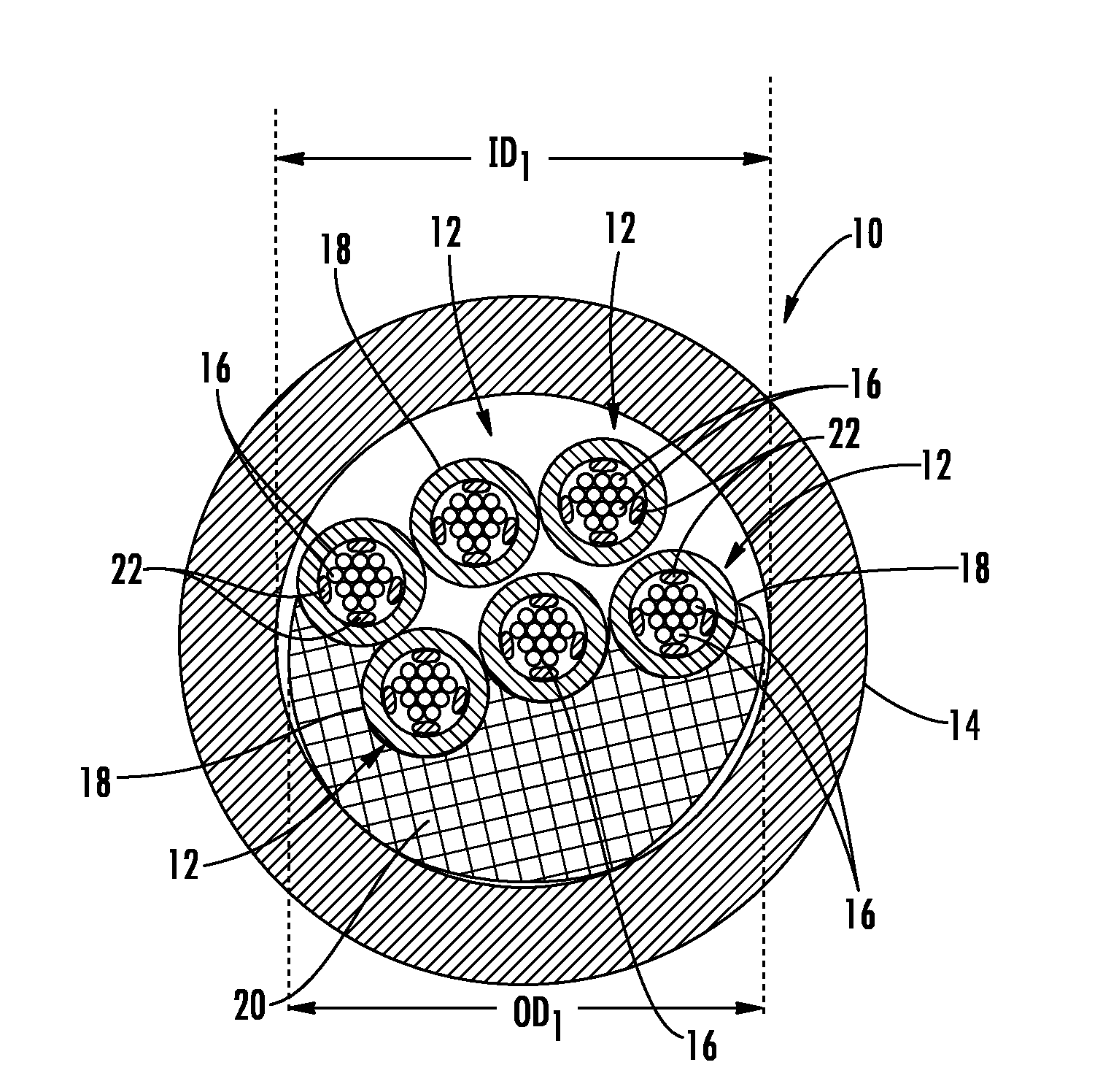
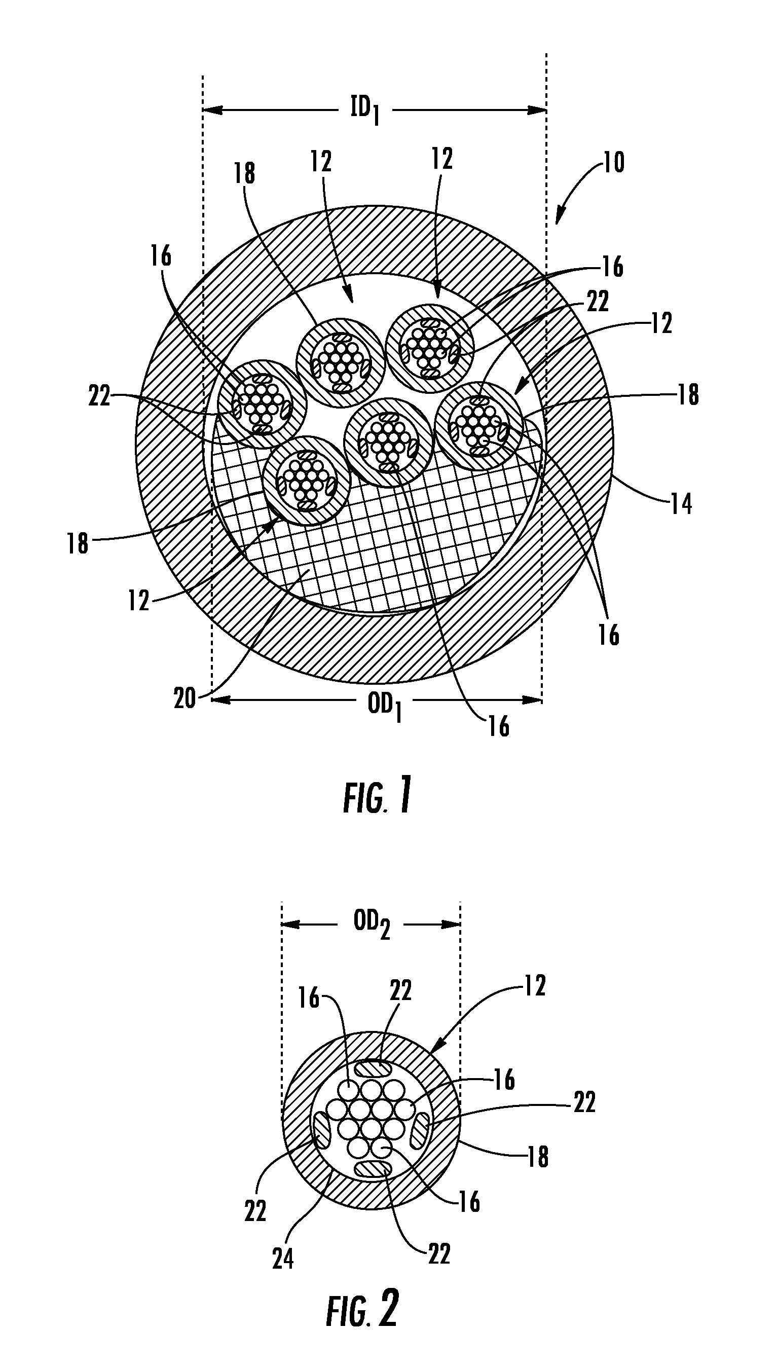
[0033]Embodiments disclosed in the detailed description include multi-fiber, fiber optic cables providing constrained optical fibers within an optical fiber sub-unit disposed in a cable jacket. Related fiber optic components and fiber optic assemblies are also disclosed. In one embodiment, one or more optical fiber sub-units can be provided that each comprises a plurality of optical fibers disposed adjacent one or more sub-unit strength members within a sub-unit jacket. Movement of optical fibers within a s...


PUM

PropertyMeasurementUnit
inner diameter ID1aaaaaaaaaa
outer diameter OD2aaaaaaaaaa

Abstract

Multi-fiber, fiber optic cable assemblies and related fiber optic components, cables, and methods providing constrained optical fibers within an optical fiber sub-unit are disclosed. The optical fiber sub-unit(s) comprises optical fibers disposed adjacent a sub-unit strength member(s) within a sub-unit jacket. Movement of optical fibers within a sub-unit jacket can be constrained. In this manner, the optical fibers in an optical fiber sub-unit can be held together within the optical fiber sub-unit as a unit. As a non-limiting example, the optical fiber sub-unit(s) may be exposed and constrained in a furcation assembly as opposed to the optical fibers, thereby reducing complexity in fiber optic cable assembly preparations. Constraining the optical fibers may also allow optical skew, reduction of entanglement between the optical fibers and the cable strength members to reduce or avoid optical attenuation, and / or allow the optical fibers to act as anti-buckling components within the fiber optic cable.

Description

PRIORITY APPLICATION[0001]This is a continuation of U.S. patent application Ser. No. 13 / 165,974, filed on Jun. 22, 2011, the content of which is relied upon and incorporated herein by reference in its entirety, and the benefit of priority under 35 U.S.C. §120 is hereby claimed.BACKGROUND[0002]1. Field of the Disclosure[0003]The technology of the disclosure relates to multi-fiber, fiber optic cables, and related fiber optic components and assemblies.[0004]2. Technical Background[0005]Benefits of optical fiber use include extremely wide bandwidth and low noise operation. Because of these advantages, optical fiber is increasingly being used for a variety of applications, including but not limited to broadband voice, video, and data transmission. As a result, fiber optic communications networks include a number of interconnection points at which multiple optical fibers are interconnected. Fiber optic communications networks also include a number of connection terminals, examples of whic...

Claims


Application Information

Patent Timeline
Patent Type & Authority Applications(United States)
IPC IPC(8): G02B6/44G02B6/46
CPCG02B6/443G02B6/4486G02B6/46G02B6/4472G02B6/4434Y10T29/49826Y10T29/49117G02B6/441G02B6/4432
Inventor HURLEY, WILLIAM CARLYATES, WESLEY ALLAN
Owner CORNING OPTICAL COMM LLC
Why Eureka
Try Eureka