Composite girder partially reinforced with carbon fiber reinforced polymer

Inactive Publication Date: 2015-01-15
KING FAHD UNIVERSITY OF PETROLEUM AND MINERALS
View PDF6 Cites 9 Cited by
  • Summary
  • Abstract
  • Description
  • Claims
  • Application Information

AI Technical Summary

Benefits of technology

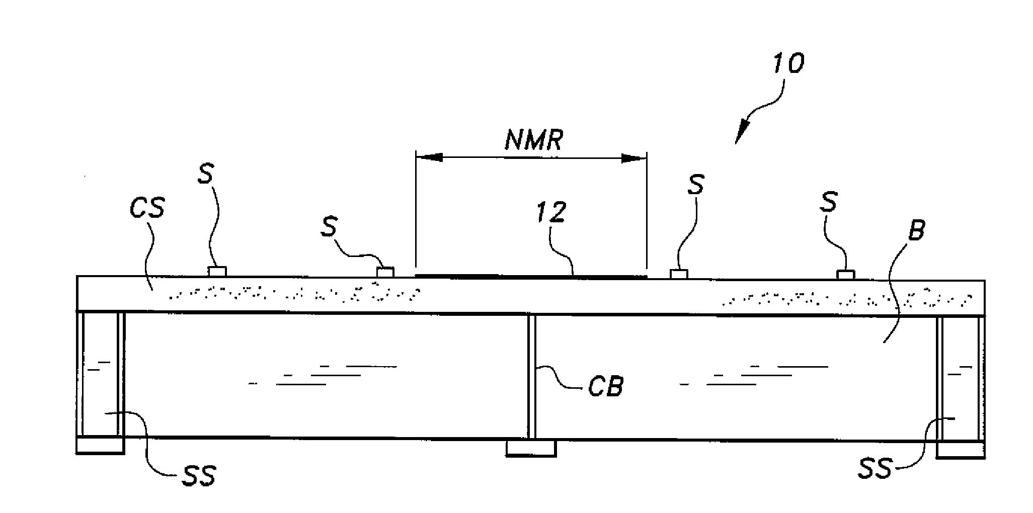
[0011]The composite girder partially reinforced with carbon fiber reinforced polymer includes a steel beam having upper and lower flanges connected by a web, and a concrete slab having opposed upper and lower surfaces, such that the lower surface of the slab is secured to the upper flange of the steel beam (either an I-beam or an H-beam) to form a composite concrete-steel girder. A layer of carbon fiber reinforced polymer is secured to the upper

Problems solved by technology

Failure in bending will occur when the bending moment is sufficient to induce tensile st

Method used


Image

  • Composite girder partially reinforced with carbon fiber reinforced polymer
  • Composite girder partially reinforced with carbon fiber reinforced polymer
  • Composite girder partially reinforced with carbon fiber reinforced polymer

Examples


Embodiment Construction

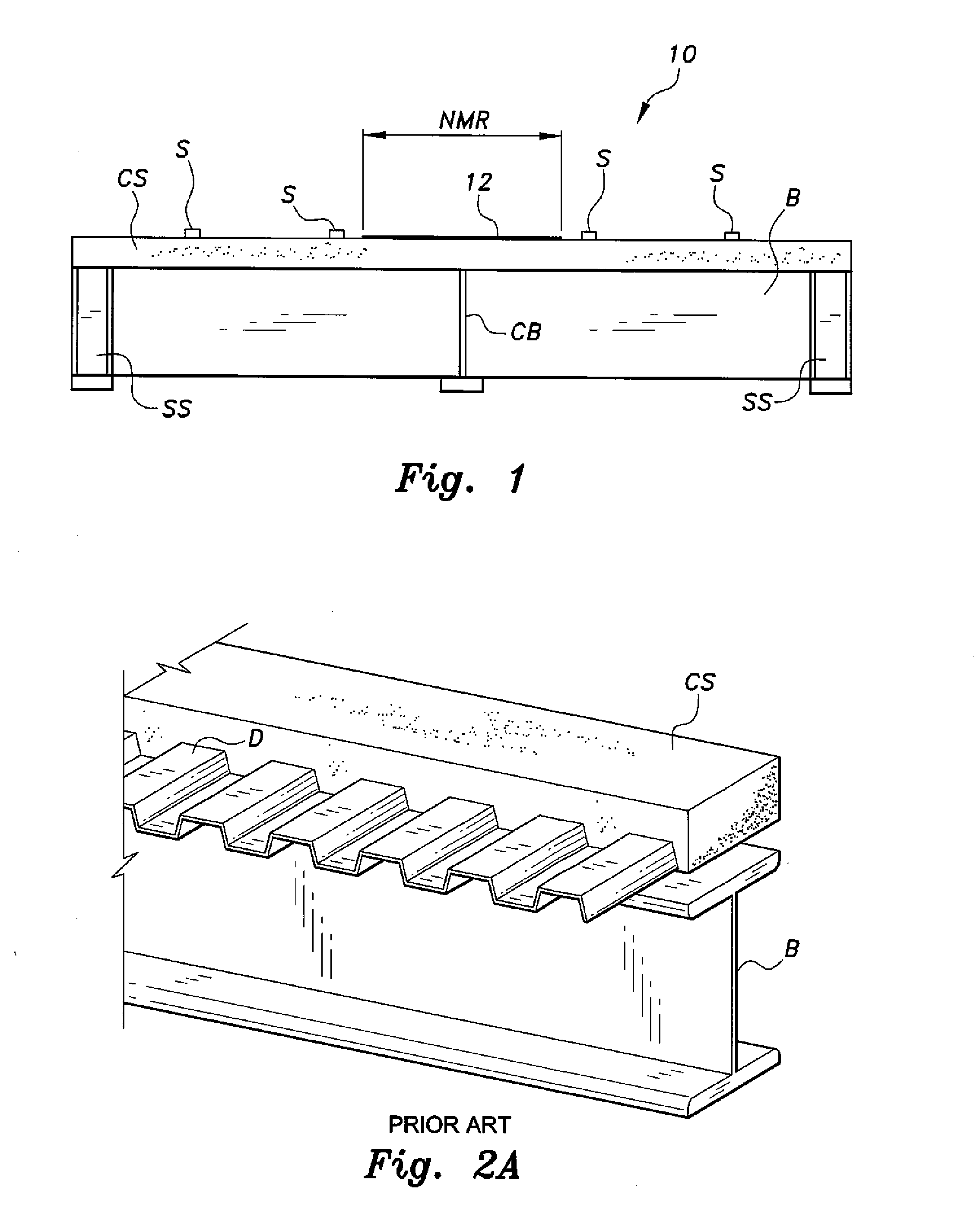
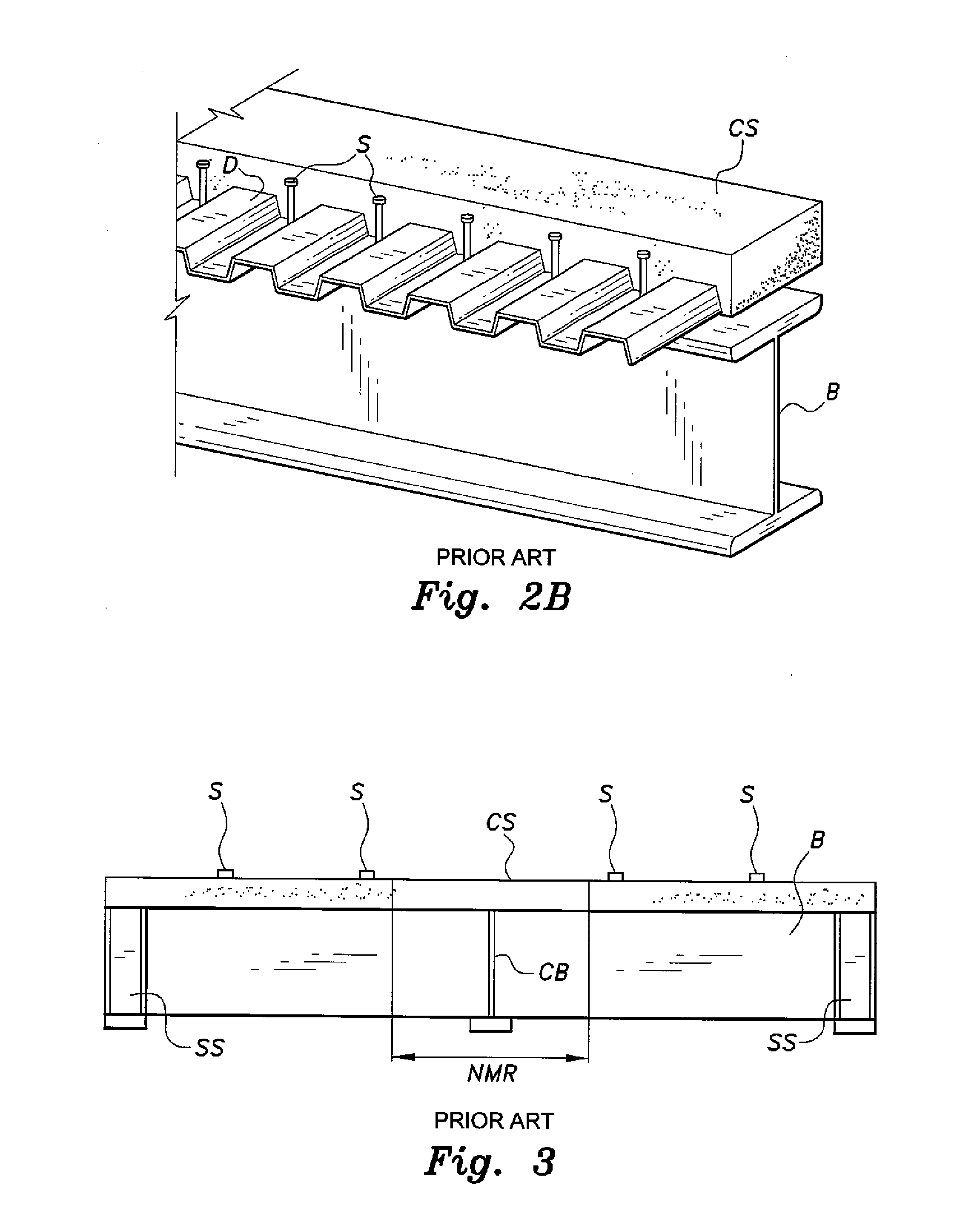
[0022]The composite girder partially reinforced with carbon fiber reinforced polymer (CFRP) 10, as shown in FIG. 1, is similar to the prior art steel-concrete composite beam shown in FIG. 3, but with a layer 12 of carbon fiber reinforced polymer mounted on the upper surface of concrete slab CS and extending across the negative moment region NMR. For a conventional composite construction girder having a length of 9.6 m, the NMR has a length of about 2.36 m; i.e., extending 1.18 m along either side of the fulcrum point of cross beam CB. The polymer is preferably epoxy, although polyester, vinyl ester, or nylon may be used. The sheet of CFRP is bonded to the concrete slab by an adhesive, which is preferably a 2-part epoxy impregnation resin, although any suitable concrete adhesive may be used.

[0023]In order to examine the effectiveness of the carbon fiber reinforced polymer layer 12 a finite element analysis was performed, comparing a conventional continuous composite steel-concrete (C...


PUM


Abstract

The composite girder partially reinforced with carbon fiber reinforced polymer is a composite steel-concrete beam partially reinforced with a sheet of carbon fiber reinforced polymer bonded to a concrete slab secured to a flange of the steel beam by shear studs, the sheet of CFRP extending across the length and width of the negative moment region of the beam. The negative moment region may be centered about a point of interior support of the composite steel-concrete beam. The carbon fiber reinforced polymer may have a thickness of about 0.25 mm.

Description

BACKGROUND OF THE INVENTION[0001]1. Field of the Invention[0002]The present invention relates to construction elements and supports, and particularly to a composite girder partially reinforced with carbon fiber reinforced polymer that provides a composite steel-concrete beam or girder that is reinforced with a layer of carbon fiber reinforced polymer over a negative moment region of the composite steel-concrete girder.[0003]2. Description of the Related Art[0004]As shown in FIG. 2A, conventional steel beams B are typically used to carry a concrete slab CS supported by a metal deck D. FIG. 2A illustrates typical non-composite construction, in which the beam B does not interact structurally with the concrete slab CS; i.e., the concrete slab is essentially dead weight on the metal deck D disposed between the slab CS and the steel beam B. This is because the slab CS is not adequately bonded to the beam B. In contrast, as shown in FIG. 2B, in composite construction, the concrete slab CS ...

Claims


Application Information

Patent Timeline
IPC IPC(8): E04C3/10
CPCE04C3/10E04B5/40E04C3/29
Inventor SHARIF, ALFARABISAMAANEH, MOHAMMAD ABDULRAHMAN
Owner KING FAHD UNIVERSITY OF PETROLEUM AND MINERALS
Why Eureka
Try Eureka