
Variable valve timing control device for internal combustion engine

a technology of variable valve timing and control device, which is applied in the direction of electric control, engine starter, machine/engine, etc., can solve the problem of valve timing not being held

Active Publication Date: 2015-01-15
NISSAN MOTOR CO LTD
View PDF1 Cites 2 Cited by
  • Summary
  • Abstract
  • Description
  • Claims
  • Application Information

AI Technical Summary

Benefits of technology

The patent allows for holding an engine valve in a specific position even at high engine speeds. This allows for better control of the engine's valve timing, improving its performance.

Problems solved by technology

However, when an engine revolution speed increases and thus a centrifugal force, acting on the lock pin, also increases, there is a possibility that valve timing may not be held at the intermediate lock position by the use of the intermediate lock mechanism.

Method used


Image

  • Variable valve timing control device for internal combustion engine
  • Variable valve timing control device for internal combustion engine
  • Variable valve timing control device for internal combustion engine

Examples


case 1

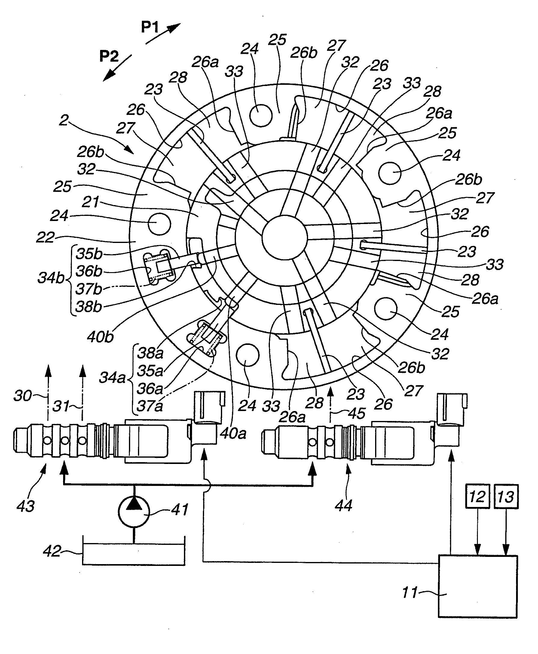
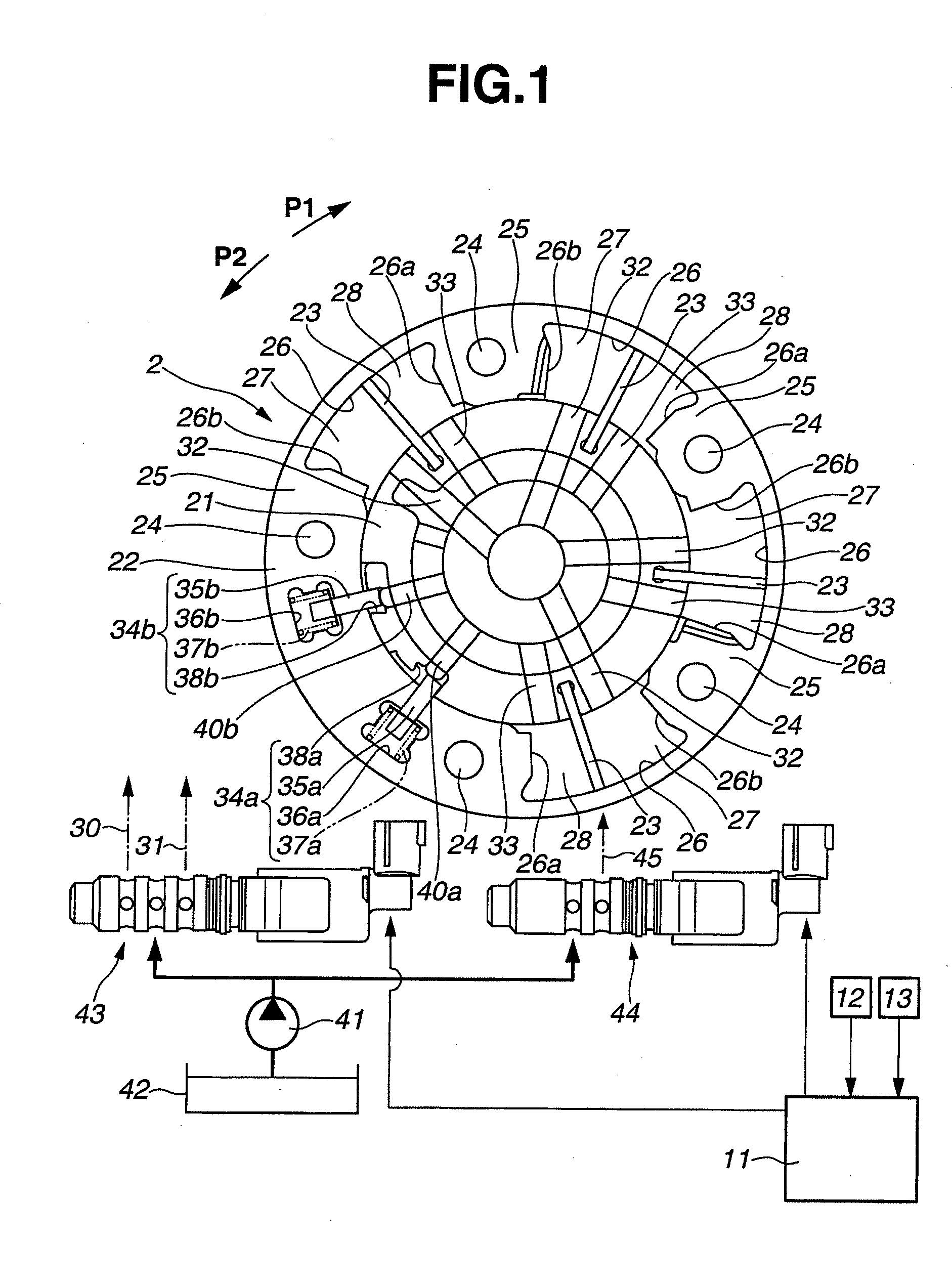
[0100] The valve timing of the intake valve immediately after the top ends of lock keys 35a, 35b and the engaging recessed portions 38a, 38b have been disengaged from each other exists on the phase-retard side with respect to the intermediate lock position, and thus the valve timing of the intake valve is operating toward the phase-advance side. Thereafter, however, the valve timing of the intake valve has shifted to the phase-advance side with respect to the intermediate lock position without engaging the top ends of lock keys 35a, 35b with respective engaging recessed portions 38a, 38b at the intermediate lock position.

case 2

[0101] The valve timing of the intake valve immediately after the top ends of lock keys 35a, 35b and the engaging recessed portions 38a, 38b have been disengaged from each other exists on the phase-advance side with respect to the intermediate lock position, from the beginning.

[0102]For instance, suppose that the valve timing of the intake valve is not held at the intermediate lock position mechanically by means of intermediate lock mechanisms 34a, 34b, even though the valve timing of the intake valve has to be mechanically held at the intermediate lock position by means of intermediate lock mechanisms 34a, 34b during a stop of the internal combustion engine, caused by turn-off operation of the engine key by the driver. In such a case, as soon as a predetermined time (for example, one second) has elapsed from the turn-off operation of the engine key, the internal combustion engine stops for preventing the driver from feeling discomfort. With the internal combustion engine put in a s...


PUM


Abstract

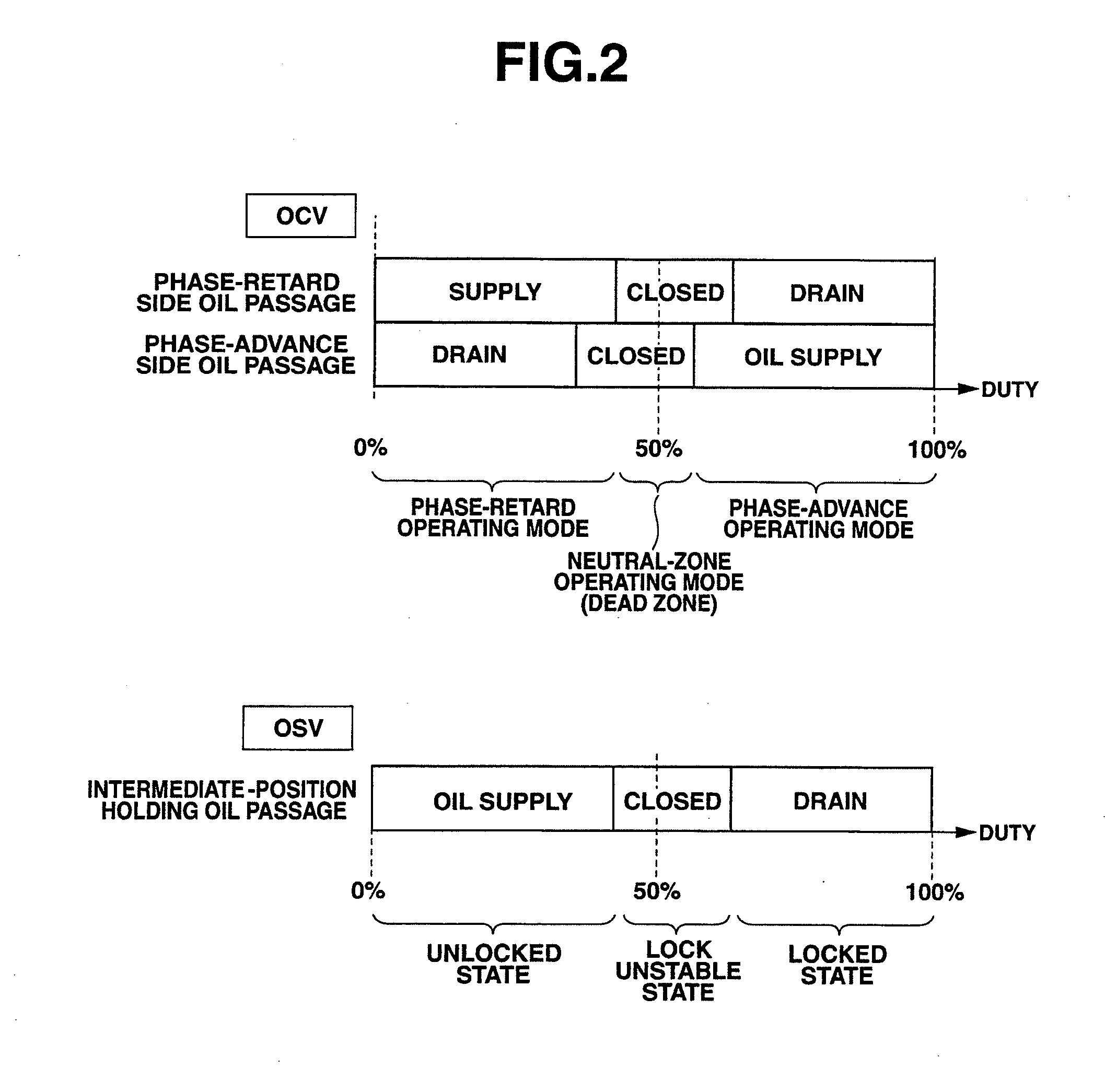
Intermediate position feedback control is executed when valve timing of an intake valve is at an intermediate lock position, an intermediate lock is needed, and an engine revolution speed is greater than a first engine revolution speed R1. Forced lock control is executed when the valve timing of the intake valve is at the intermediate lock position, the intermediate lock is needed, the engine revolution speed is less than the first engine revolution speed R1, and the intermediate position feedback control is not being executed. As a result, even when the engine revolution speed increases in the presence of a demand that the valve timing needs to be in the intermediate lock position, it is possible to maintain the valve timing at the intermediate lock position.

Description

TECHNICAL FIELD[0001]The present invention relates to a variable valve timing control device for an internal combustion engine.BACKGROUND ART[0002]Patent document 1 discloses a variable valve timing device of an internal combustion engine, which is provided with an intermediate lock mechanism that enables a phase of a camshaft relative to a crankshaft to be locked at an intermediate phase.[0003]The intermediate lock mechanism, disclosed in the Patent document 1, has a housing configured to rotate in synchronism with the crankshaft, vanes installed in the housing and configured to rotate together with the camshaft, and a lock pin configured to extend along the direction perpendicular to the camshaft. The intermediate lock mechanism is configured to restrict relative rotation of the camshaft with respect to the crankshaft and hold valve timing at a predetermined intermediate lock position, by inserting the lock pin from the camshaft side into a lock hole formed in the housing.[0004]Ho...

Claims


Application Information

Patent Timeline
Patent Type & Authority Applications(United States)
IPC IPC(8): F02D13/02
CPCF02D13/02F02D13/0219F02D13/0238F01L1/3442F01L2001/34426F01L2001/34466F01L2001/34473F02D2013/0292F02D41/062F02D41/1401F02D41/2451F02N19/004F02D2041/001F02D2200/101Y02T10/12
Inventor ITO, HIRONORIITOYAMA, HIROYUKIARIGA, KENJISHIOZAWA, KEN
Owner NISSAN MOTOR CO LTD
Learn More