

Wellbore composite plug assembly
- Summary
- Abstract
- Description
- Claims
- Application Information
AI Technical Summary
Benefits of technology
Problems solved by technology
Method used
Image

Examples
Embodiment Construction
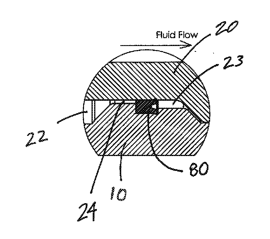
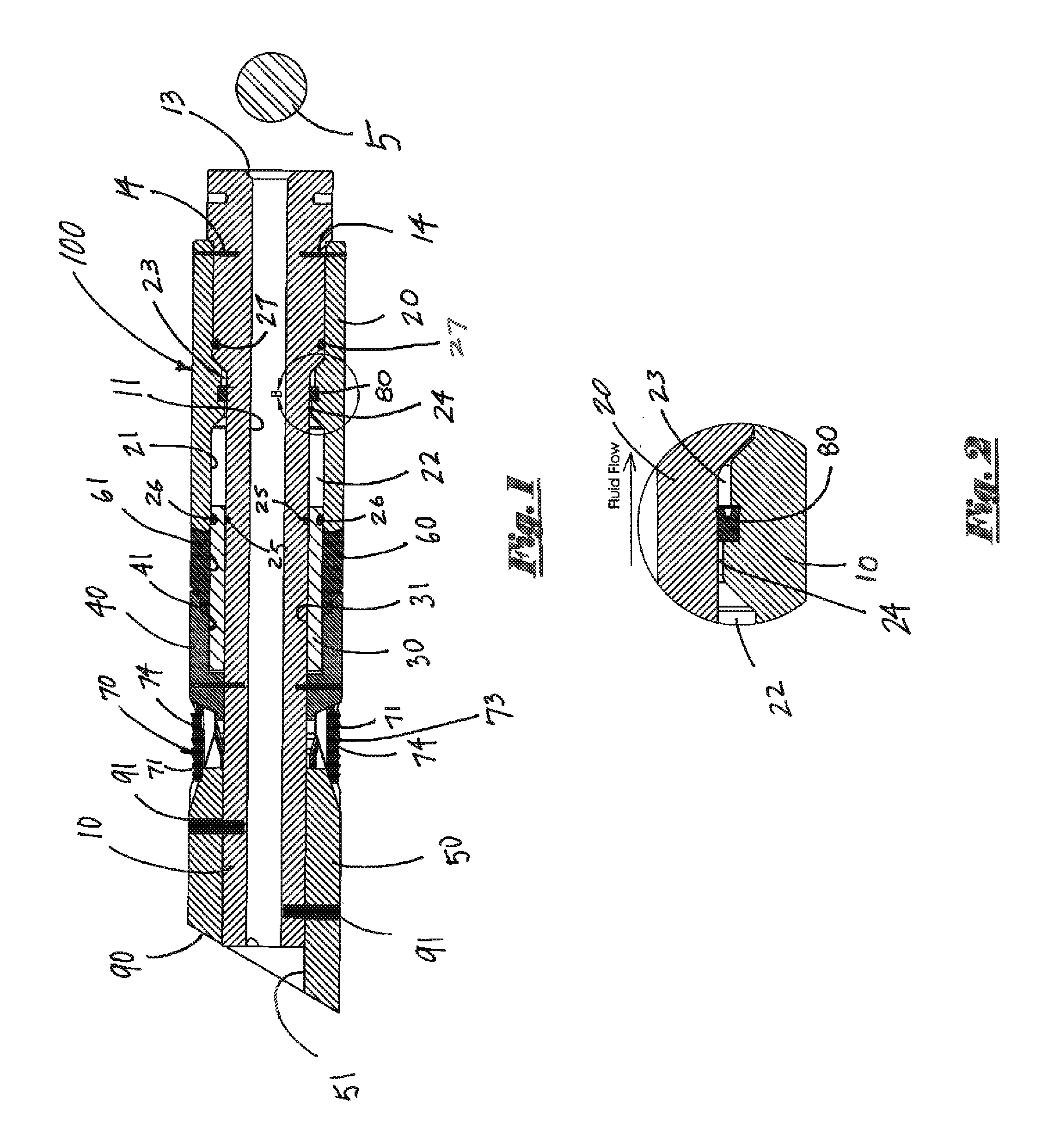
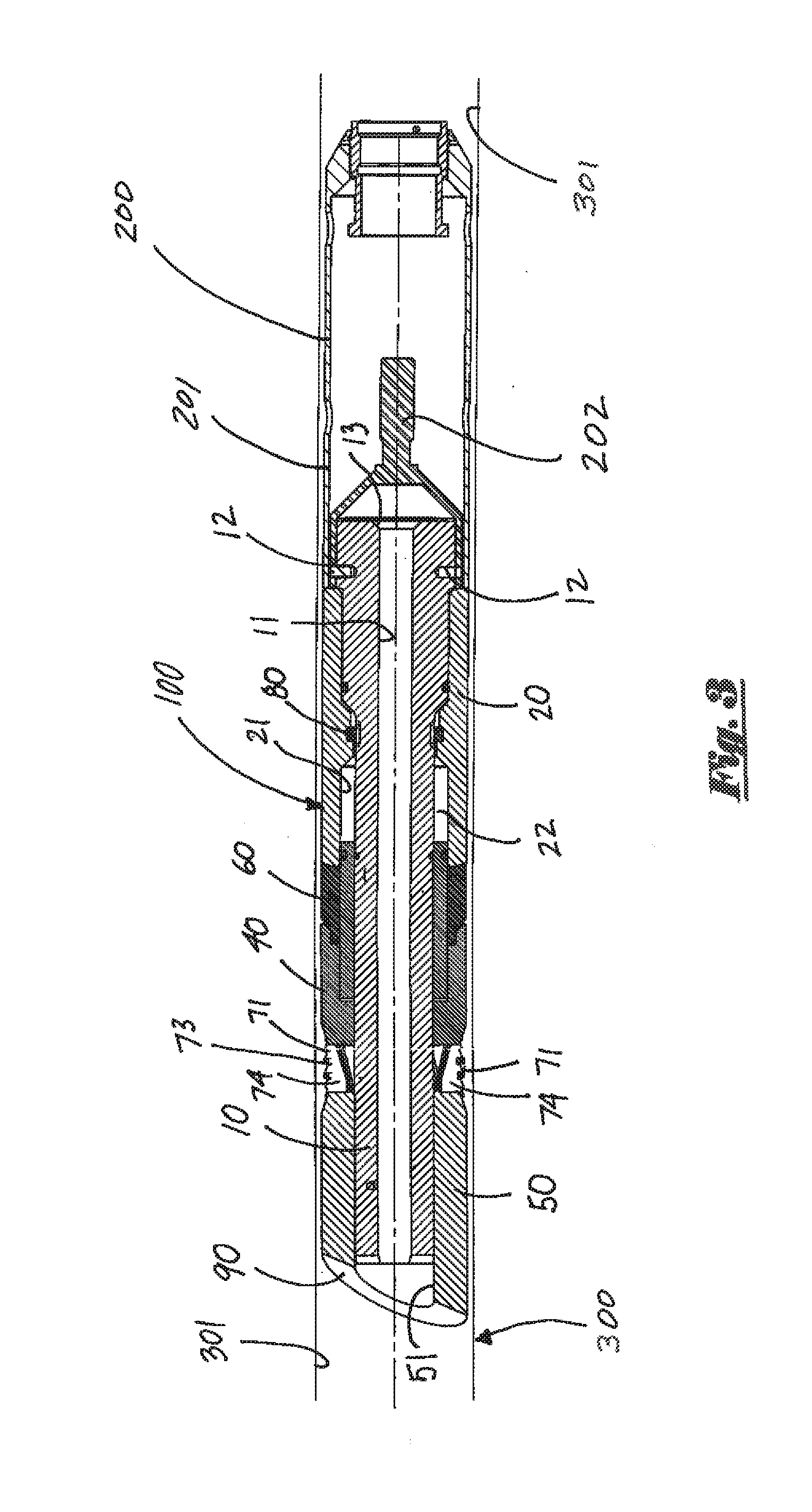
[0032]The present invention comprises a plug assembly for down hole use in wellbores such as, for example, in oil or gas wells that penetrate subterranean formations. In a preferred embodiment, certain components of the plug assembly of the present invention can be beneficially manufactured from at least one material that can be relatively quickly and efficiently milled, drilled or otherwise mechanically broken apart such as, for example, composite resin impregnated fiber or other material exhibiting similar characteristics.
[0033]The plug assembly of the present invention can be installed to selectively isolate one portion of a wellbore from another, to prevent fluid flow from one portion of a wellbore to another and / or to provide a fluid pressure sealing barrier at a desired location within a wellbore. The plug assembly of the present invention can be beneficially set within the internal bore of a string of casing, production tubing or other tubular. However, it is to be observed t...
PUM
 Abstract
Description
Claims
Application Information