Techniques for optimizing stencil buffers

Active Publication Date: 2015-01-15
NVIDIA CORP
View PDF3 Cites 3 Cited by
  • Summary
  • Abstract
  • Description
  • Claims
  • Application Information

AI Technical Summary

Benefits of technology

[0010]One advantage of the disclosed techniques is that stencil buffers are optimally-sized based on the requirements of the software application. In particular, the amount of physical memory used to store stencil bu

Problems solved by technology

One limitation to using stencil buffers in a binary fashion is that the stencil buffer requires a relatively large amount of sparsely-accessed memory.
Consequently, 122 bits per pixel of memory would be wasted.
Because the local memory

Method used


Image

  • Techniques for optimizing stencil buffers
  • Techniques for optimizing stencil buffers
  • Techniques for optimizing stencil buffers

Examples


Embodiment Construction

[0018]In the following description, numerous specific details are set forth to provide a more thorough understanding of the present invention. However, it will be apparent to one of skill in the art that the present invention may be practiced without one or more of these specific details.

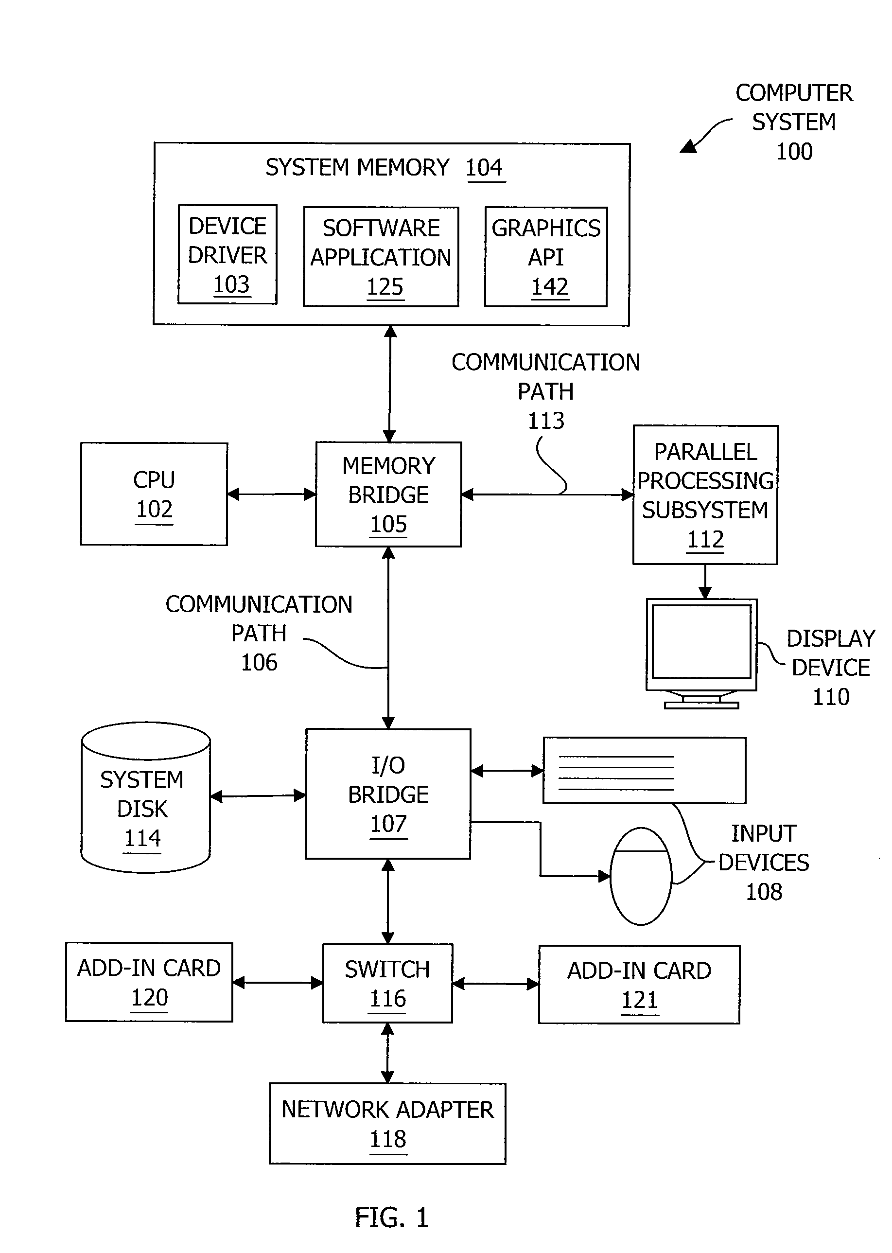
[0019]FIG. 1 is a block diagram illustrating a computer system 100 configured to implement one or more aspects of the present invention. As shown, computer system 100 includes, without limitation, a central processing unit (CPU) 102 and a system memory 104 coupled to a parallel processing subsystem 112 via a memory bridge 105 and a communication path 113. Memory bridge 105 is further coupled to an I / O (input / output) bridge 107 via a communication path 106, and I / O bridge 107 is, in turn, coupled to a switch 116.

[0020]In operation, I / O bridge 107 is configured to receive user input information from input devices 108, such as a keyboard or a mouse, and forward the input information to CPU 102 for proc...


PUM


Abstract

One embodiment sets forth a method for associating each stencil value included in a stencil buffer with multiple fragments. Components within a graphics processing pipeline use a set of stencil masks to partition the bits of each stencil value. Each stencil mask selects a different subset of bits, and each fragment is strategically associated with both a stencil value and a stencil mask. Before performing stencil actions associated with a fragment, the raster operations unit performs stencil mask operations on the operands. No fragments are associated with both the same stencil mask and the same stencil value. Consequently, no fragments are associated with the same stencil bits included in the stencil buffer. Advantageously, by reducing the number of stencil bits associated with each fragment, certain classes of software applications may reduce the wasted memory associated with stencil buffers in which each stencil value is associated with a single fragment.

Description

BACKGROUND OF THE INVENTION[0001]1. Field of the Invention[0002]Embodiments of the present invention relate generally to graphics processing and, more specifically, to techniques for optimizing stencil buffers.[0003]2. Description of the Related Art[0004]Some conventional graphics processing units (GPUs) include different processing engines configured to operate in parallel with one another to implement a graphics processing pipeline. A graphics processing pipeline is the collection of processing steps performed to transform 3-D images into rendered 2-D images. When a given processing engine finishes processing data, that processing engine may copy the processed data from local memory to a memory that is shared between the different processing engines within the GPU. Other processing engines may then access the processed data and then perform additional processing operations with that data. One type of data structure used in a graphics processing pipeline to allow different processi...

Claims


Application Information

Patent Timeline
IPC IPC(8): G06T1/60
CPCG06T1/60B41F15/34G06T11/40G06T15/005
Inventor LUM, ERIC B.DULUK, JR., JEROME F.
Owner NVIDIA CORP
Why Eureka
Try Eureka