Display panel and display device

Active Publication Date: 2015-01-15
SHARP KK
View PDF3 Cites 2 Cited by
  • Summary
  • Abstract
  • Description
  • Claims
  • Application Information

AI Technical Summary

Benefits of technology

The invention is a display panel and device with an optical modulation layer that contains a polar solvent, a nonpolar solvent, and shape-anisotropic members with hydrophilic or hydrophobic properties. The first and second substrates have hydrophilic or hydrophobic properties, respectively. By adjusting the voltage applied to the optical modulation layer, the size of the shape-anisotropic members' projected area on the substrates can be changed. This results in increased light use efficiency with a simple configuration.

Problems solved by technology

According to the configuration, most of the light emitted by the backlight is lost by being absorbed and reflected before reaching a display screen, and this causes a decrease in light use efficiency.
In particular, loss of light due to the polarizing plates significantly influences the decrease in light use efficiency.

Method used


Image

  • Display panel and display device
  • Display panel and display device
  • Display panel and display device

Examples


embodiment 1

[0087]The following description will discuss a display device in accordance with Embodiment 1 of the present invention, with reference to the drawings.

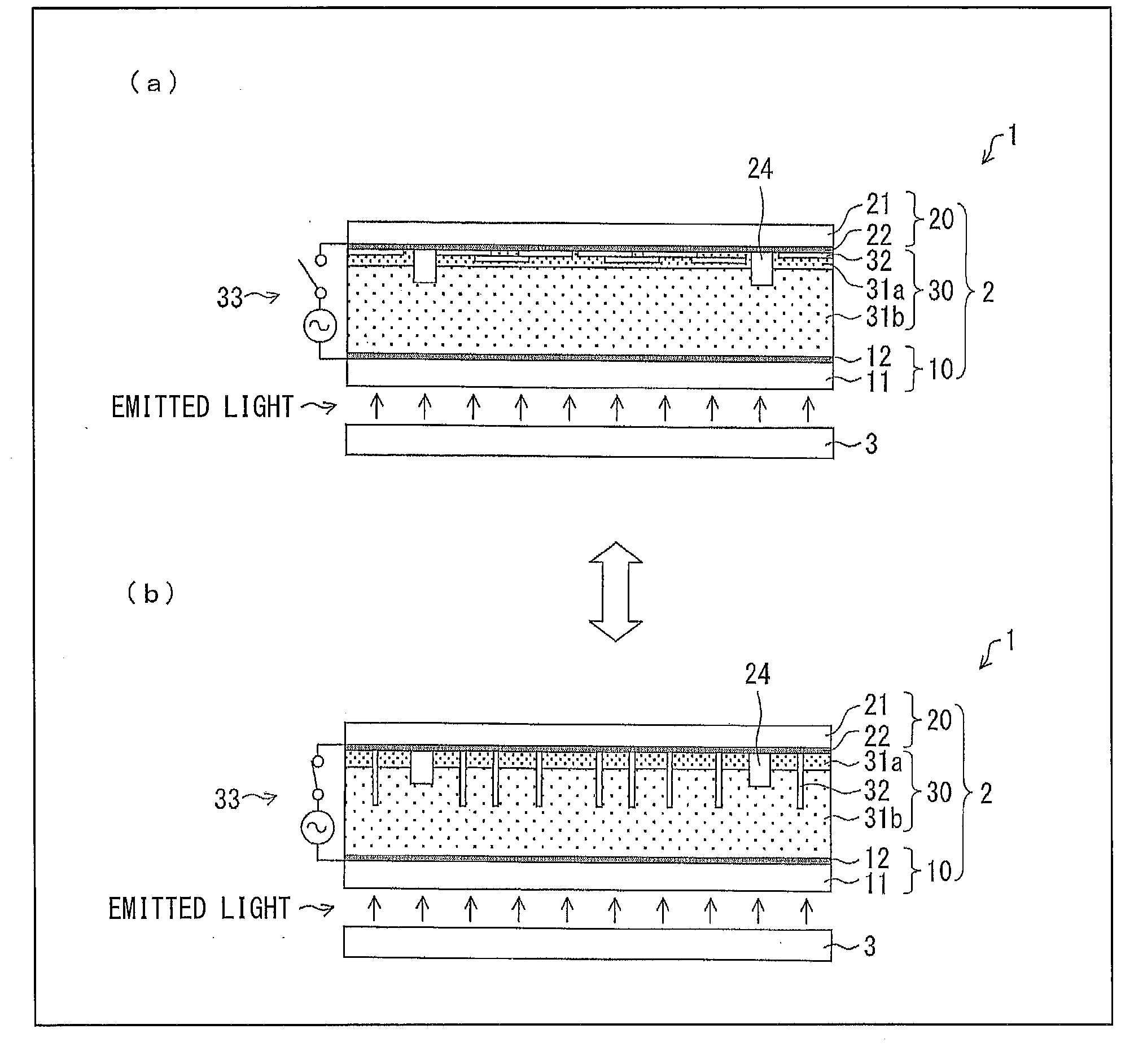
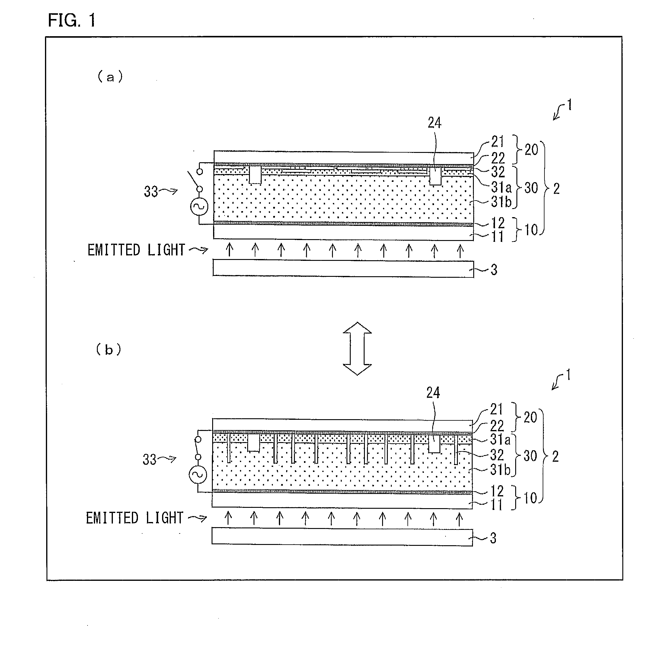
[0088]FIG. 1 is a cross-sectional view schematically illustrating, in (a) and (b), a configuration of a display device 1 in accordance with Embodiment 1. The display device 1 includes a display panel 2, a backlight 3 for irradiating the display panel 2 with light, and a driving circuit (not illustrated). The display device 1 is a transmissive display device which carries out display by allowing light, which has been emitted by the backlight 3, to pass through the display panel 2.

[0089]Note that the backlight 3 has a conventional configuration, and the configuration of the backlight 3 is not described in this specification. The backlight 3 can be, for example, an edge light surface light source device or a direct surface light source device. As a light source of the backlight 3, a fluorescent tube, an LED, or the like can be used as ap...

embodiment 2

[0131]The following description will discuss a display device in accordance with Embodiment 2 of the present invention, with reference to the drawings.

[0132]Note that the descriptions below mainly discuss differences from the display device of Embodiment 1, the same reference numerals are given to constituent elements having functions identical to those described in Embodiment 1, and such constituent elements will not be described repeatedly.

[0133]Each of (a) and (b) of FIG. 6 is a cross-sectional view schematically illustrating a configuration of a display device 1a in accordance with Embodiment 2. The display device 1a includes a display panel 2a and a driving circuit (not illustrated), and is a reflection type display device which carries out a display by reflecting outside light which has entered the display panel 2a.

[0134]The display panel 2a includes (i) substrates 10a and 20 which are arranged to face each other and (ii) an optical modulation layer 30a which is provided betw...

embodiment 3

[0156]The following description will discuss a display device in accordance with Embodiment 3 of the present invention, with reference to the drawings.

[0157]Note that the descriptions below mainly discuss differences from the display devices of Embodiments 1 and 2, the same reference numerals are given to constituent elements having functions identical to those described in Embodiments 1 and 2, and such constituent elements will not be described repeatedly.

[0158]Each of (a) and (b) of FIG. 10 is a cross-sectional view schematically illustrating a configuration of a display device 1b in accordance with Embodiment 3. The display device 1b is a so-called transflective display device (i) which includes a display panel 2b, a backlight 3 for emitting light to the display panel 2b, and a driving circuit (not illustrated) and (ii) carries out display by allowing light, emitted by the backlight 3, to pass through and carries out display by reflecting incoming outside light.

[0159]The display ...


PUM


Abstract

The present invention provides a display panel and a display device which can increase light use efficiency with a simple configuration. An optical modulation layer 30 provided between substrates 10 and 20 contains a polar solvent 31a, a nonpolar solvent 31b, and hydrophilic shape-anisotropic members 32, the hydrophilic substrate makes contact with the polar solvent 31a, the hydrophobic substrate 10 makes contact with the nonpolar solvent 31b, a projected area of the shape-anisotropic members 32 onto the substrates 10 and 20 is changed by adjusting a magnitude of a voltage to be applied to the optical modulation layer 30.

Description

TECHNICAL FIELD[0001]The present invention relates to a display panel and a display device.BACKGROUND ART[0002]A conventional liquid crystal display panel mainly includes a pair of glass substrates, a liquid crystal layer provided between the glass substrates, electrodes provided on the glass substrates, and polarizing plates attached to the respective glass substrates. On such a liquid crystal display panel, an image is recognized by contrasts which appear on a screen by light that has been emitted by a backlight and has then passed through the polarizing plates and the liquid crystal layer. According to the configuration, most of the light emitted by the backlight is lost by being absorbed and reflected before reaching a display screen, and this causes a decrease in light use efficiency. In particular, loss of light due to the polarizing plates significantly influences the decrease in light use efficiency.[0003]Patent Literature 1 discloses an optical device (i) which includes a p...

Claims


Application Information

Patent Timeline
IPC IPC(8): G02F1/167G02F1/19G02F1/1339G02F1/169
CPCG02F1/13394G02F1/167G02F1/19G02B26/026G02B26/023G02F1/169
Inventor SATOH, EIJINAKAMURA, KOHZOHWATANABE, HISASHINAKAHARA, TAKAHIRO
Owner SHARP KK
Why Eureka
Try Eureka