Power converter
- Summary
- Abstract
- Description
- Claims
- Application Information
AI Technical Summary
Benefits of technology
Problems solved by technology
Method used
Image
Examples
first embodiment
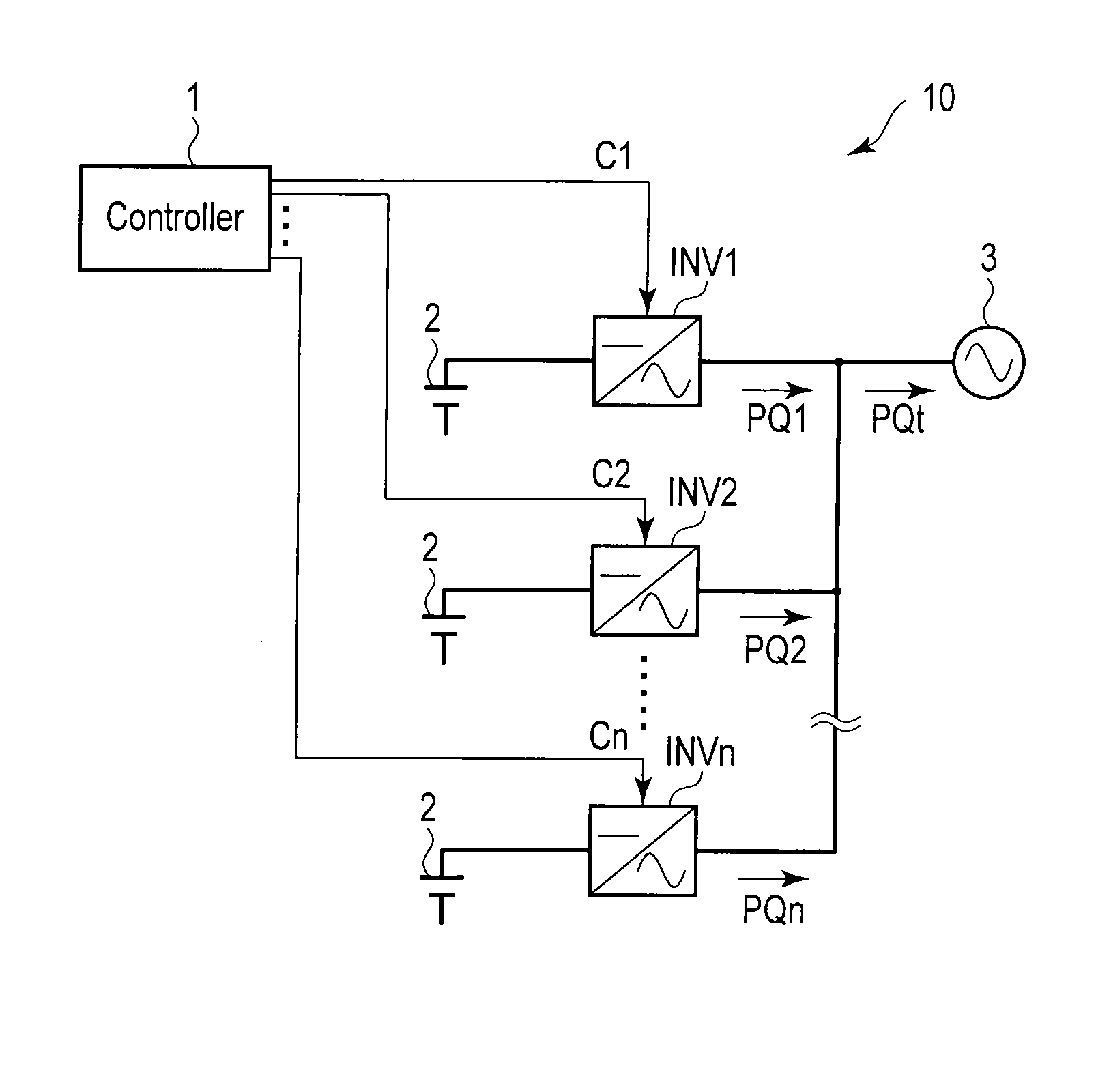
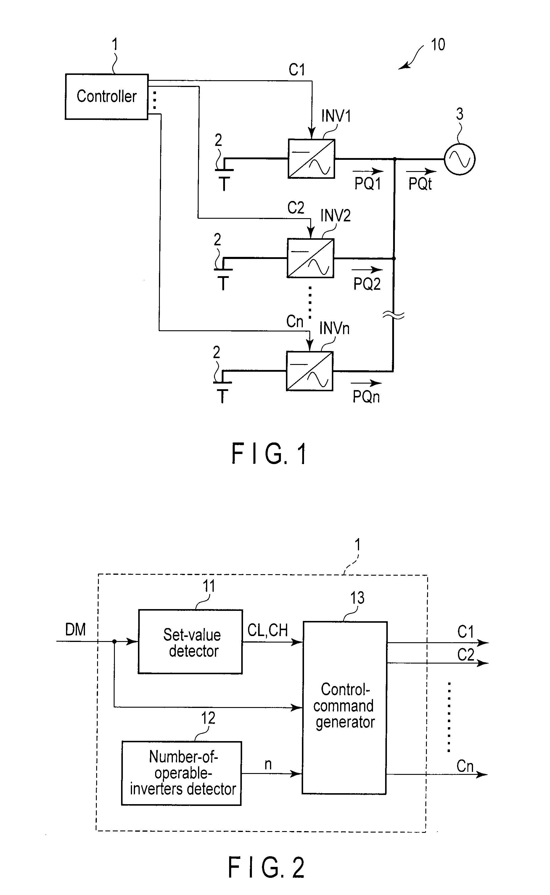
[0016]FIG. 1 is a structural view showing a structure of a power conversion system 10 according to a first embodiment of the present invention. Also, the same portions in the drawings are given the same signs, the detailed explanations thereof will be omitted, and different portions will be mainly described. Also in the following embodiment, overlapping explanations will be omitted.
[0017]The power conversion system 10 includes a controller 1, n direct current (DC) power sources 2, an AC power system 3, and n inverters INV1 to INVn. Here, n is an integer greater than one.
[0018]To DC sides of the inverters INV1 to INVn, the DC power sources 2 are connected, respectively. AC sides of all the inverters INV1 to INVn are connected to the AC power system 3. The inverters INV1 to INVn convert DC power supplied from the DC power sources 2 into AC power and supply it to the AC power system 3. The inverters INV1 to INVn are controlled in accordance with control command values C1 to Cn output f...
second embodiment
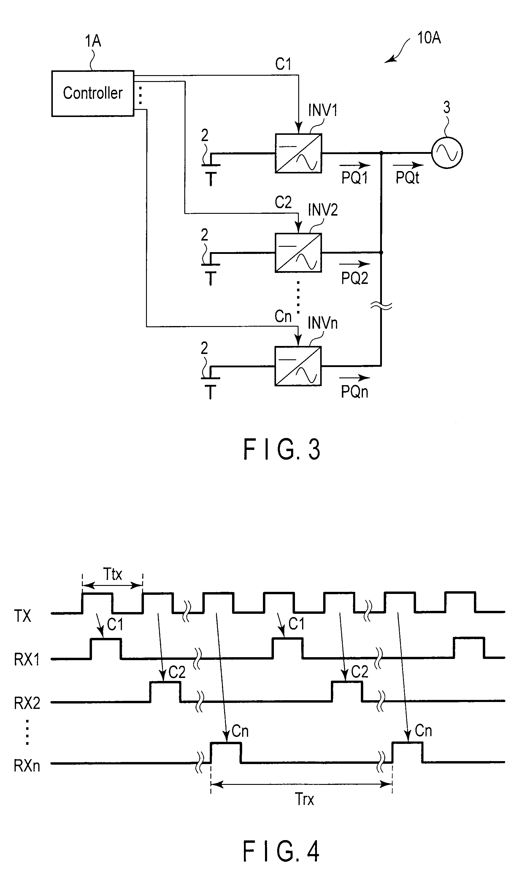
[0051]FIG. 3 is a structural view showing a structure of a power conversion system 10A according to a second embodiment of the present invention.
[0052]The power conversion system 10A is obtained by replacing the controller 1 with a controller 1A in the power conversion system 10 according to the first embodiment shown in FIG. 1. With respect to the other points, the power conversion system 10A has the same structure as that of the power conversion system 10 according to the first embodiment.
[0053]The controller 1A outputs control command values C1 to Cn to the respective inverters INV1 to INVn at regular time intervals. With respect to the other points, the controller 1A has the same structure as the controller 1 according to the first embodiment.
[0054]FIG. 4 is a waveform chart showing a relationship between a control cycle Ttx of the controller 1A and a communication cycle Trx of the inverters INV1 to INVn according to the present embodiment. A wavy form TX indicates the state of ...
PUM
 Abstract
Description
Claims
Application Information
 - R&D
- Intellectual Property
- Life Sciences
- Materials
- Tech Scout
- Unparalleled Data Quality
- Higher Quality Content
- 60% Fewer Hallucinations
Browse by: Latest US Patents, China's latest patents, Technical Efficacy Thesaurus, Application Domain, Technology Topic, Popular Technical Reports.
© 2025 PatSnap. All rights reserved.Legal|Privacy policy|Modern Slavery Act Transparency Statement|Sitemap|About US| Contact US: help@patsnap.com


