
Direct Electric Heating System for Heating a Subsea Pipeline

a heating system and subsea pipeline technology, applied in the direction of lighting, heating apparatus, borehole/well accessories, etc., can solve the problems of reducing the efficiency of conventional systems, restricting the flow, and forming hydrates, so as to improve the efficiency of power distribution and transmission, and increase the step-out distance. , the effect of reducing the loss of electric power transmission

Active Publication Date: 2015-01-15
SIEMENS ENERGY AS
View PDF4 Cites 11 Cited by
  • Summary
  • Abstract
  • Description
  • Claims
  • Application Information

AI Technical Summary

Benefits of technology

The patent describes a system for supplying power to subsea pipelines. The system includes a three-phase transformer and first electric connections to connect to the subsea power cable. The system also has second electric connections to connect to the pipeline section for heating it. A symmetrisation unit is used to evenly distribute the electric load between the three phases of the transformer output, creating a balanced load on the power source. The system may also include feeder connection points along the subsea power cable for further distribution of power to the subsea DEH modules. Overall, the system provides an effective and simple solution for power distribution in subsea applications.

Problems solved by technology

This may lead to the formation of hydrates that may be a combination of pressurized hydrocarbon gas with water.
Hydrates may restrict the flow within a pipeline, or may even completely plug the pipeline.
The problem of conventional systems is that the conventional systems are generally restricted to rather short distances between the pipeline section to be heated and the power supply.
Also, the length of the pipeline to be heated is only very limited.
Long step-out distances may thus generally not be realized.
Such systems may lack any way of controlling the heating.
Also, there are significant losses of electric energy along the subsea cable to the pipeline, and the subsea cable itself is a very cost intensive product.

Method used


Image

  • Direct Electric Heating System for Heating a Subsea Pipeline
  • Direct Electric Heating System for Heating a Subsea Pipeline
  • Direct Electric Heating System for Heating a Subsea Pipeline

Examples


Embodiment Construction

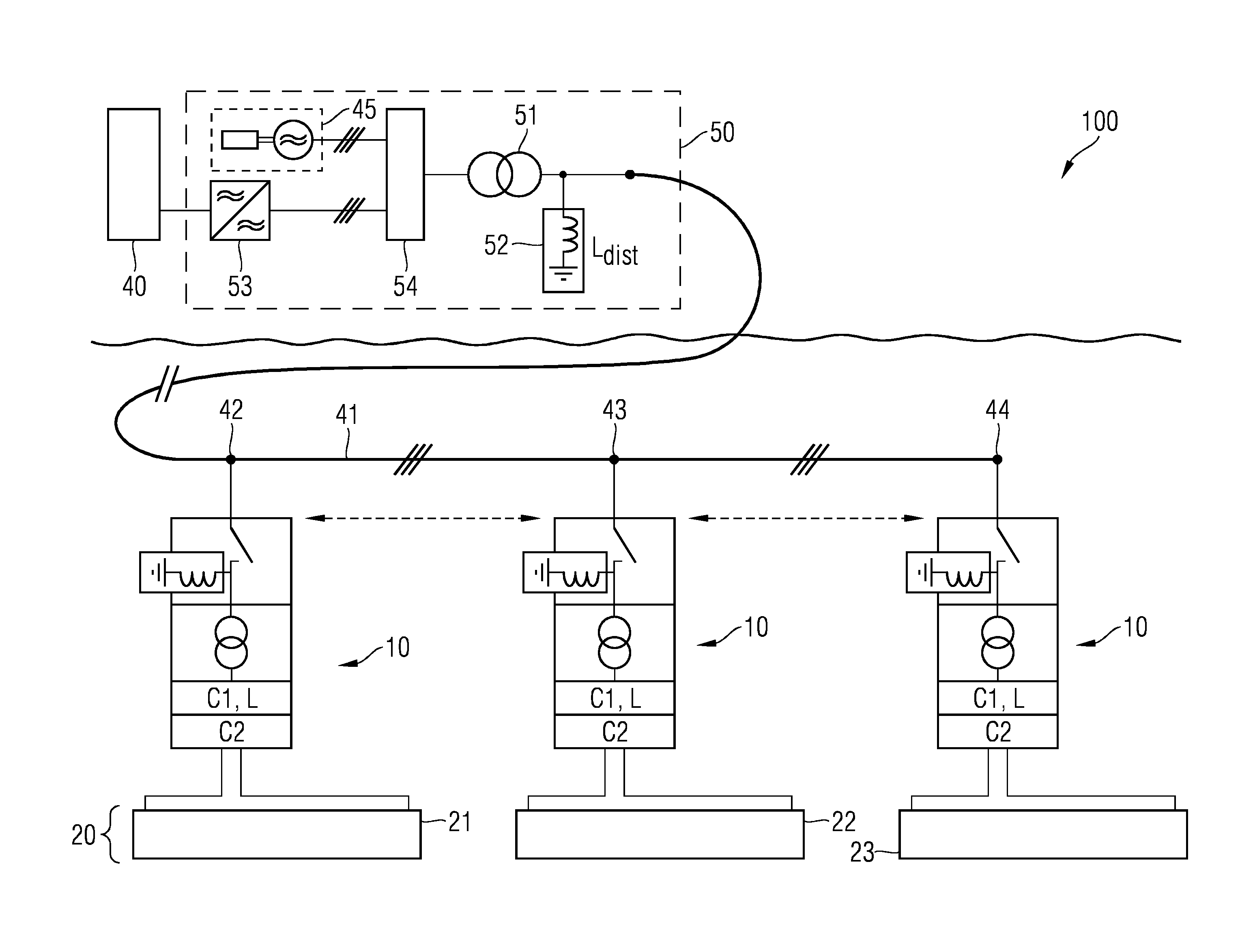
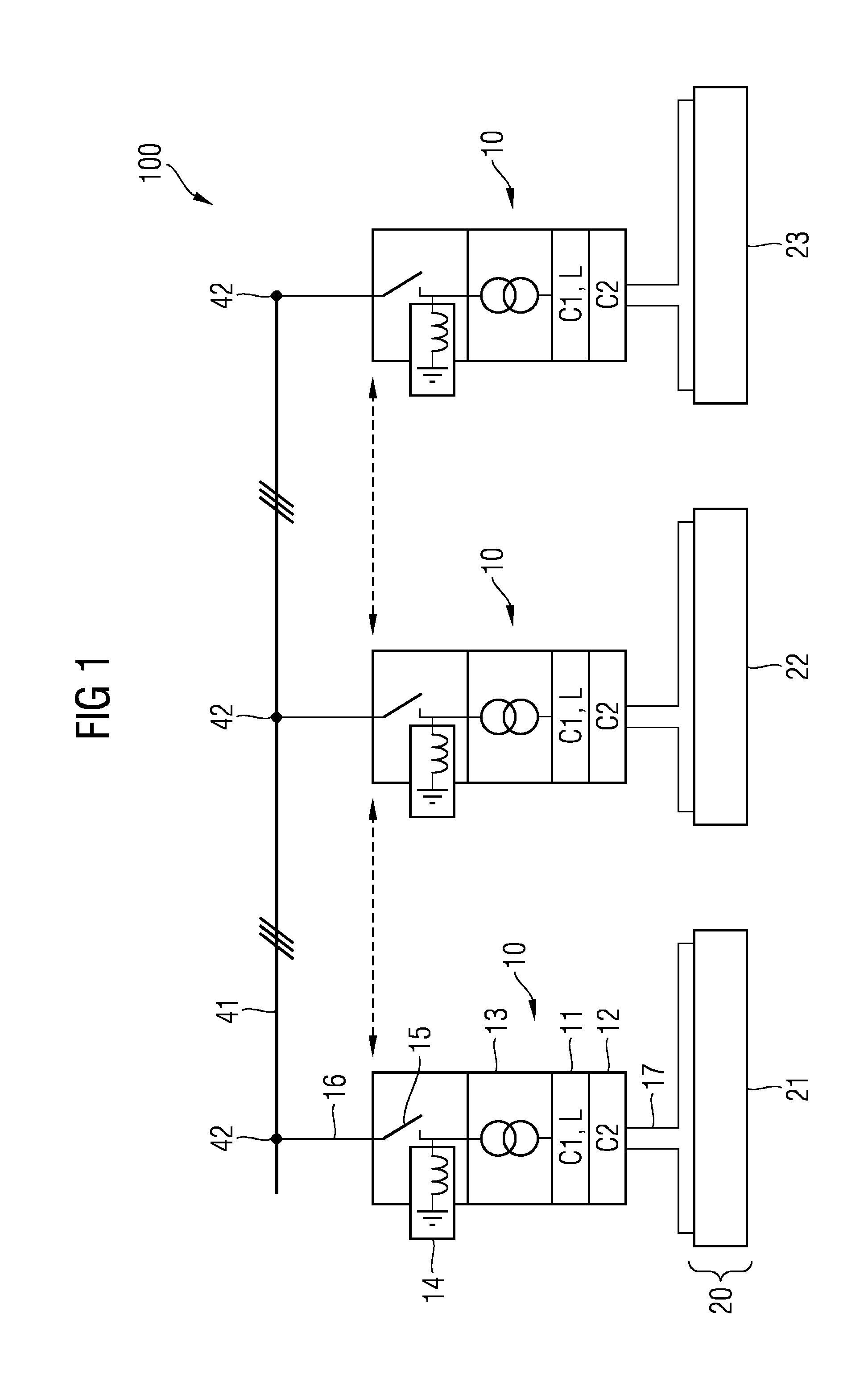
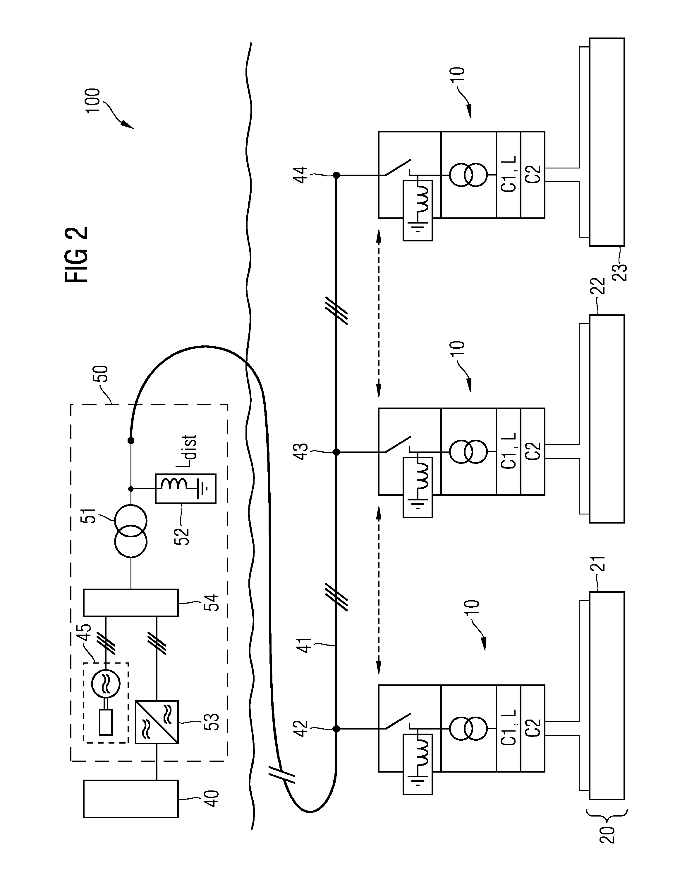
[0048]In the following, embodiments will be described in detail with reference to the accompanying drawings. The following description of embodiments is given only for the purpose of illustration and is not to be taken in a limiting sense.

[0049]The drawings are to be regarded as being schematic representations only, and elements in the drawings are not necessarily to scale with each other. Also, the coupling of physical or functional units as shown in the drawings and described hereinafter may not be a direct connection or coupling, but may also be an indirect connection or coupling (e.g., a connection or a coupling with one or more additional intervening elements). The physical or functional units illustrated and described herein with respect to the different embodiments may not be implemented as physically separate units. One or more physical or functional blocks or units may be implemented in a common circuit, circuit element or unit, while other physical or functional blocks or ...


PUM


Abstract

A direct electric heating (DEH) system for heating a subsea pipeline is provided. The DEH system includes a subsea power cable adapted to be coupled to a three phase electric power source. The DEH system further includes two or more subsea DEH modules. Each subsea module of the two or more subsea DEH modules is provided for heating a different pipeline section of the subsea pipeline.

Description

[0001]This application is the National Stage of International Application No. PCT / EP2012 / 074429, filed Dec. 5, 2012, which claims the benefit of European Patent Application No. EP 12153321.0, filed Jan. 31, 2012. The entire contents of these documents are hereby incorporated herein by reference.FIELD[0002]The present embodiments relate to a direct electric heating system for heating a subsea pipeline.BACKGROUND[0003]Recently, there has been an increasing interest in offshore hydrocarbon production. Hydrocarbon wells may be located many miles from shore sites and in water depths reaching down to several thousand meters. Subsea pipelines may be used for transporting hydrocarbons from an offshore well to a production vessel or to an onshore site, or may be used for transporting hydrocarbons between different onshore sites separated by an offshore section.[0004]In deep waters, the water temperature is relatively low. The water temperature may, for example, be between about −1 and +4° C....

Claims


Application Information

Patent Timeline
IPC IPC(8): F16L53/00E21B36/04H02J3/18F16L53/37
CPCH02J3/18E21B36/04F16L53/007H02J3/26Y02E40/50F16L53/37Y02E40/30
Inventor RADAN, DAMIRRASCH, BJORN
Owner SIEMENS ENERGY AS
Learn More