
Automatic fire targeting and extinguishing system and method

a fire targeting and extinguishing system technology, applied in the direction of computer control, program control, instruments, etc., can solve the problems of limited capacity of portable fire extinguishers, user in significant danger, and the danger of using portable extinguishers

Inactive Publication Date: 2015-01-22
FIRESTRIKE IND
View PDF4 Cites 27 Cited by
  • Summary
  • Abstract
  • Description
  • Claims
  • Application Information

AI Technical Summary

Benefits of technology

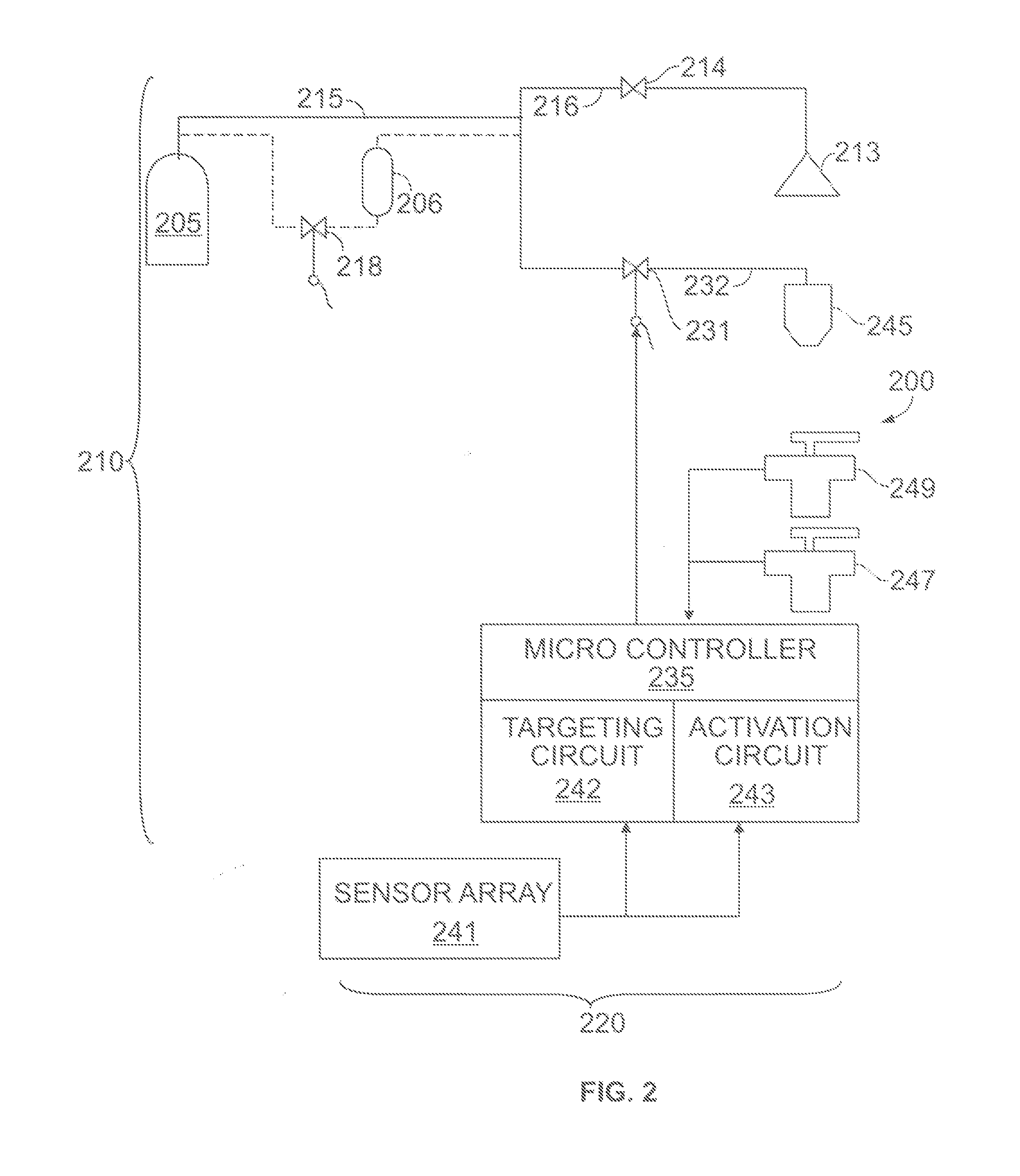
The present invention provides an automatic fire extinguishing system with a targeting system and a microcontroller to control the system. The system uses a tank filled with extinguishing agent and a plurality of temperature sensors to position the emitter. The microcontroller calculates target angles based on the temperature data and sends it to the targeting servos. The system also sends an open signal to the actuation valve when a sensor temperature exceeds a predetermined value. The extinguishing agent flows from the tank to the emitter, discharging it. The technical effect of the invention is an efficient and effective fire extinguishing system with a targeting system that can rapidly position the emitter for extinguishing fire.

Problems solved by technology

Second, the user must be in close proximity to the fire to discharge the extinguishing agent with any effectiveness, usually less than 10 feet, this puts the user in significant danger.
The larger the size and more developed the fire has become the more dangerous the use of a portable extinguisher becomes.
Further, the portable fire extinguisher has a limited capacity, usually 30-45 seconds of discharge.
This limited capacity may be sufficient for small fires that are detected quickly after initiation, but has virtually no effect for more developed fires.
Another drawback of the portable extinguisher is the extinguishing agent may be for a specific class of fire and not suitable, for extinguishing the detected fire, without increased risk to the user.
The drawback of the sprinkler system is the continuous application of extinguishing agent, such as water, does not stop until the water main is isolated from the sprinkler system.
Further, in systems where the initiation of one sprinkler head activates other sprinkler heads, unaffected areas are subjected to the significant water release.
The damage done to property from the discharged water is much more than from the fire, and includes flooding of unaffected areas and the floors below.
The drawback to the self-contained sprinkler system is the agent is not directed to a specific area, but is discharged over a general area, limiting the effectiveness of the extinguishing agent.
The drawback to these systems is the danger to personnel, because any person in the space during or immediately after the discharge will asphyxiate without breathing protection.
Further, this embodiment is limited to infrared fire detection.
The prior art has failed to supply a simple fire suppression system that maximizes the effectiveness of the extinguishing agent minimizes the risk to personnel and property, and maximizes reliability.

Method used


Image

  • Automatic fire targeting and extinguishing system and method
  • Automatic fire targeting and extinguishing system and method
  • Automatic fire targeting and extinguishing system and method

Examples


Embodiment Construction

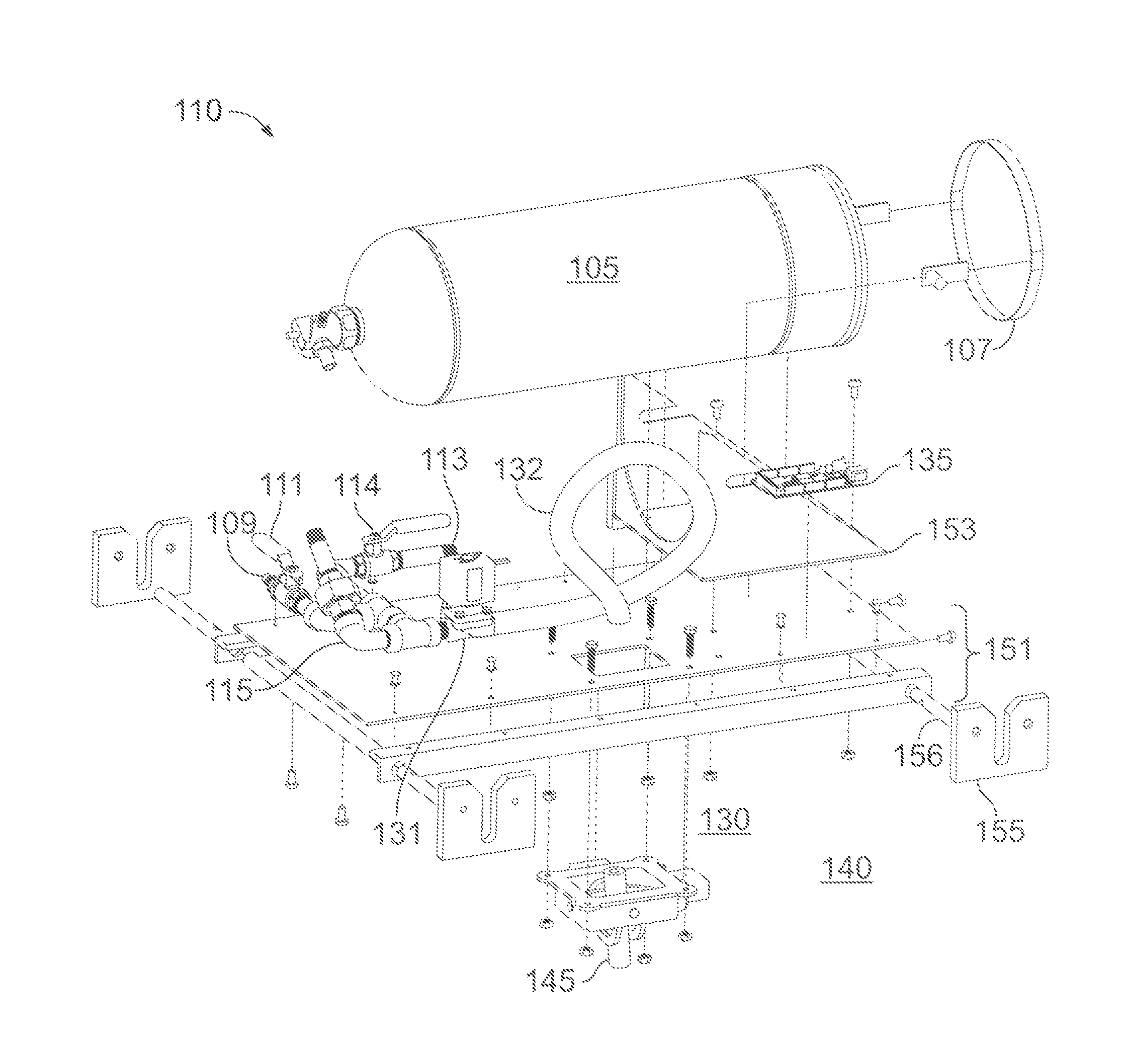
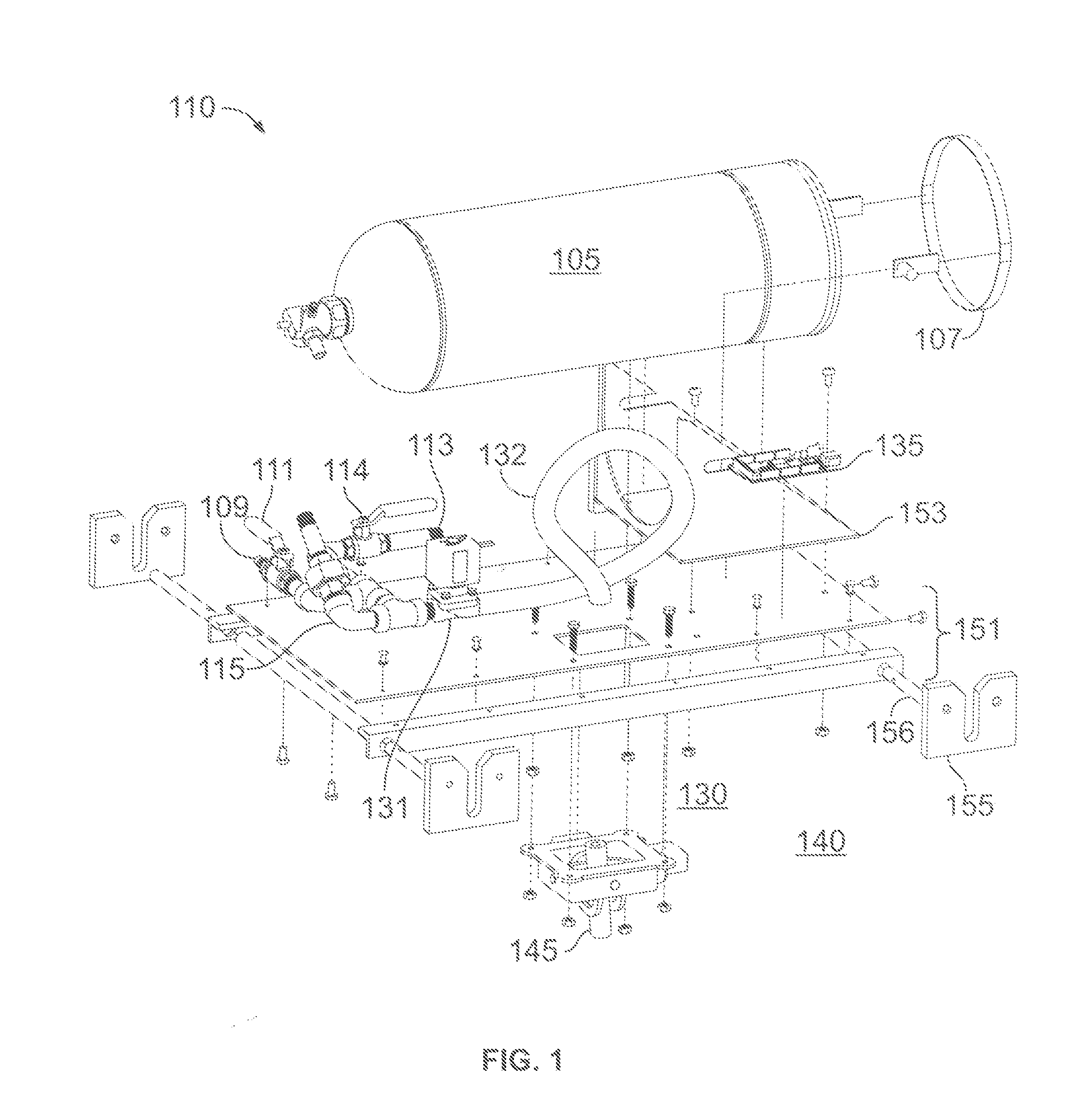
[0024]FIG. 1 illustrates an extinguishing agent emission system 100 according to an embodiment of the present invention. The extinguishing agent emission system 100 includes an agent storage system 110, an actuation system 130, a targeting system 140, and a support unit 150. The agent storage system 110 includes a pressure tank 105, a retention strap 107, a charging port 109, a charging port valve 111, a sprinkler head 113, a sprinkler head isolation valve 114, and pressurized piping 115. The actuation system 130 includes an actuation valve 131, and flexible piping 132. The targeting system 140 includes a control circuit 135 and an emitter 145. The targeting system 140 also includes a gimbal base 344, a first targeting armature 346, a first targeting servo 347, a second targeting armature 348, and a second targeting servo 349 illustrated in FIG. 3. The support unit 150 includes a foundation 151, support pins 156, mounting brackets 155, and a tank support bracket 153.

[0025]The mounti...


PUM


Abstract

A system for providing an automatic fire extinguishing system including a tank filled with an extinguishing agent with a targeting system with independently mounted targeting servos and targeting gimbal to position an emitter. A microcontroller provides control signals to the targeting servos and an actuation valve. A plurality of temperature sensors electrically connected to the microcontroller send temperature data to the microcontroller which calculates target angles and sends the target angle to the targeting gimbal. The emitter is positioned by the targeting servo positioning the targeting gimbal armatures to the target angles. The microcontroller compares sensor temperature data a predetermined temperature value and sends an open signal to the actuation valve when a sensor temperature data is greater than the predetermined temperature value. The extinguishing agent flows from the tank to the emitter, where it is discharged.

Description

BACKGROUND OF THE INVENTION[0001]The present invention relates to an automatic fire targeting and extinguishing system and method.[0002]There are a myriad of fire extinguishing systems that are well known in the art. Most predominantly is the self-contained portable fire extinguisher. The portable fire extinguisher has an extinguishing agent in a sealed tank that is either pressurized or has a pressurization source connected. The user arms the portable fire extinguisher and discharges the extinguishing agent on the fire. The portable fire extinguisher has several drawbacks. First and most importantly, someone must be present at the fire location to find the fire and the portable extinguisher must be accessible to the person finding the fire. Second, the user must be in close proximity to the fire to discharge the extinguishing agent with any effectiveness, usually less than 10 feet, this puts the user in significant danger. The larger the size and more developed the fire has become ...

Claims


Application Information

Patent Timeline
Patent Type & Authority Applications(United States)
IPC IPC(8): G05D16/20A62C37/36G05B19/048
CPCA62C37/04A62C37/36G05B2219/24015G05D16/20G05B19/048A62C31/28A62C35/023A62C37/40
Inventor MCNAMARA, IAN EDWARDRAPP, NATHAN LINDSTROMTOOMBS, NICHOLAS JOSEPHKIM, JOSHUA
Owner FIRESTRIKE IND
Learn More