Current sensor

a current sensor and sensor technology, applied in the field of current sensors, can solve problems such as difficulty in obtaining a current sensor having good accuracy, and achieve the effect of further enhancing detection accuracy

Inactive Publication Date: 2015-01-22
ALPS ALPINE CO LTD
View PDF3 Cites 21 Cited by
  • Summary
  • Abstract
  • Description
  • Claims
  • Application Information

AI Technical Summary

Benefits of technology

[0021]According to this, using the magnetic shielding member, it is possible to block the external magnetic field entering from the sensitivity axis direction, which has the most influence on a sensitivity. Furthermore, the intensity of the external magnetic field entering from a direction perpendicular to the sensitivity axis direction changes depending on the distance thereof, and the direction of the external magnetic field is aligned if the external magnetic field moves far away from an incident position. From this, the external magnetic fields of the same amplitude are incident upon the individual magnetoelectric conversion elements configuri

Problems solved by technology

In this way, in a case where the magnetic resistance elements 93 having the sensitivity-influencing axis directions are used, it is difficult for the configuration of the

Method used


Image

  • Current sensor
  • Current sensor
  • Current sensor

Examples


first embodiment

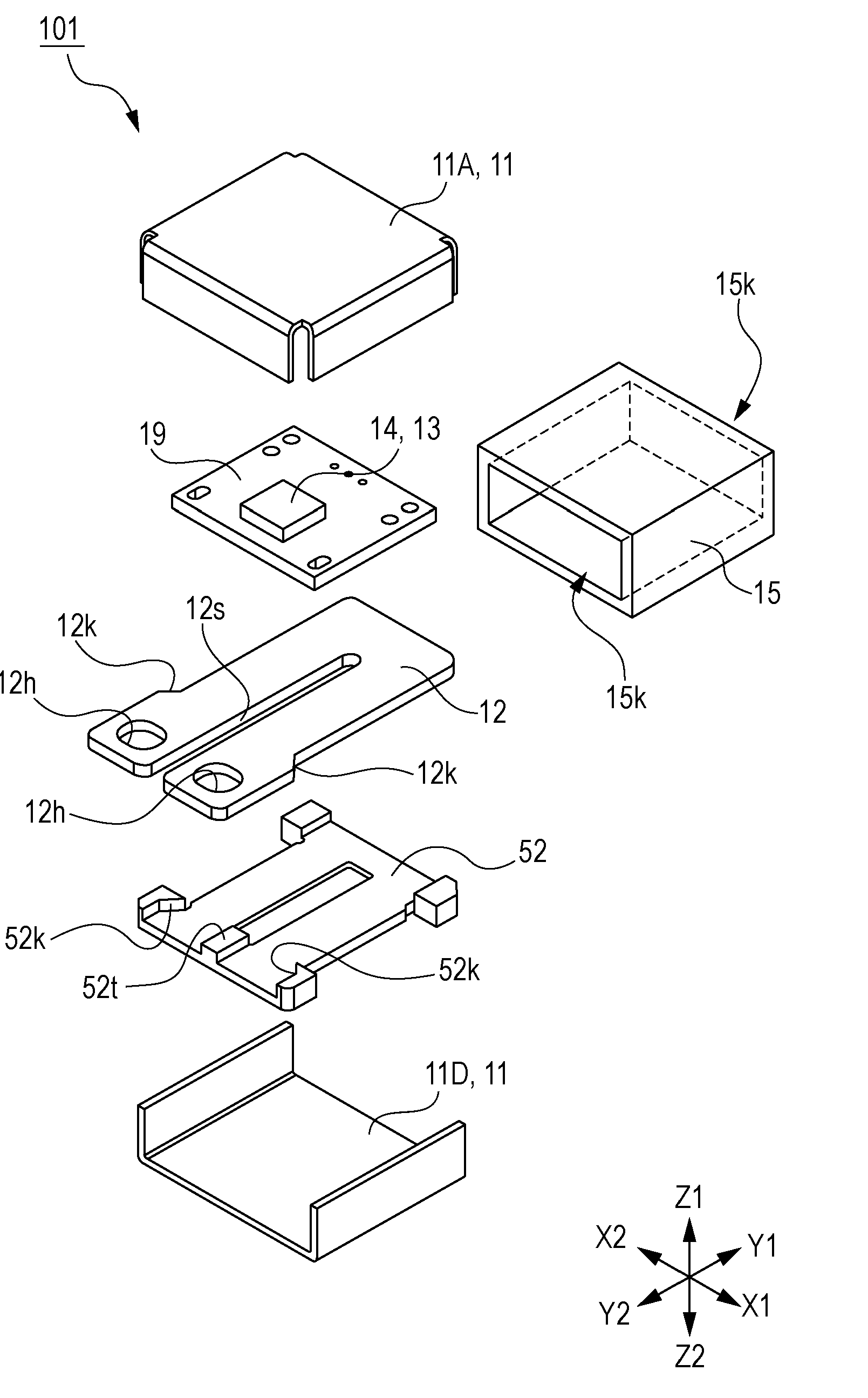
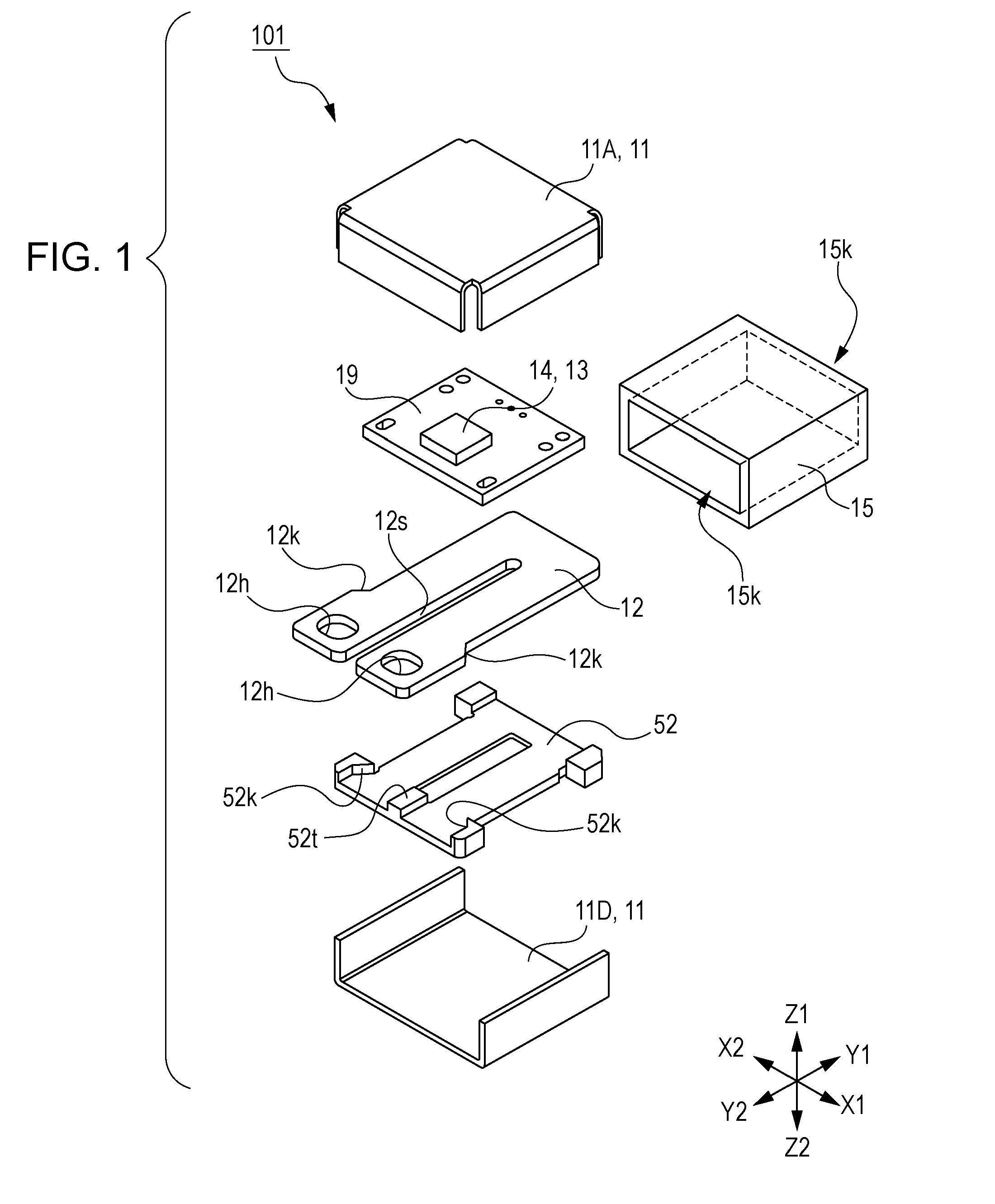
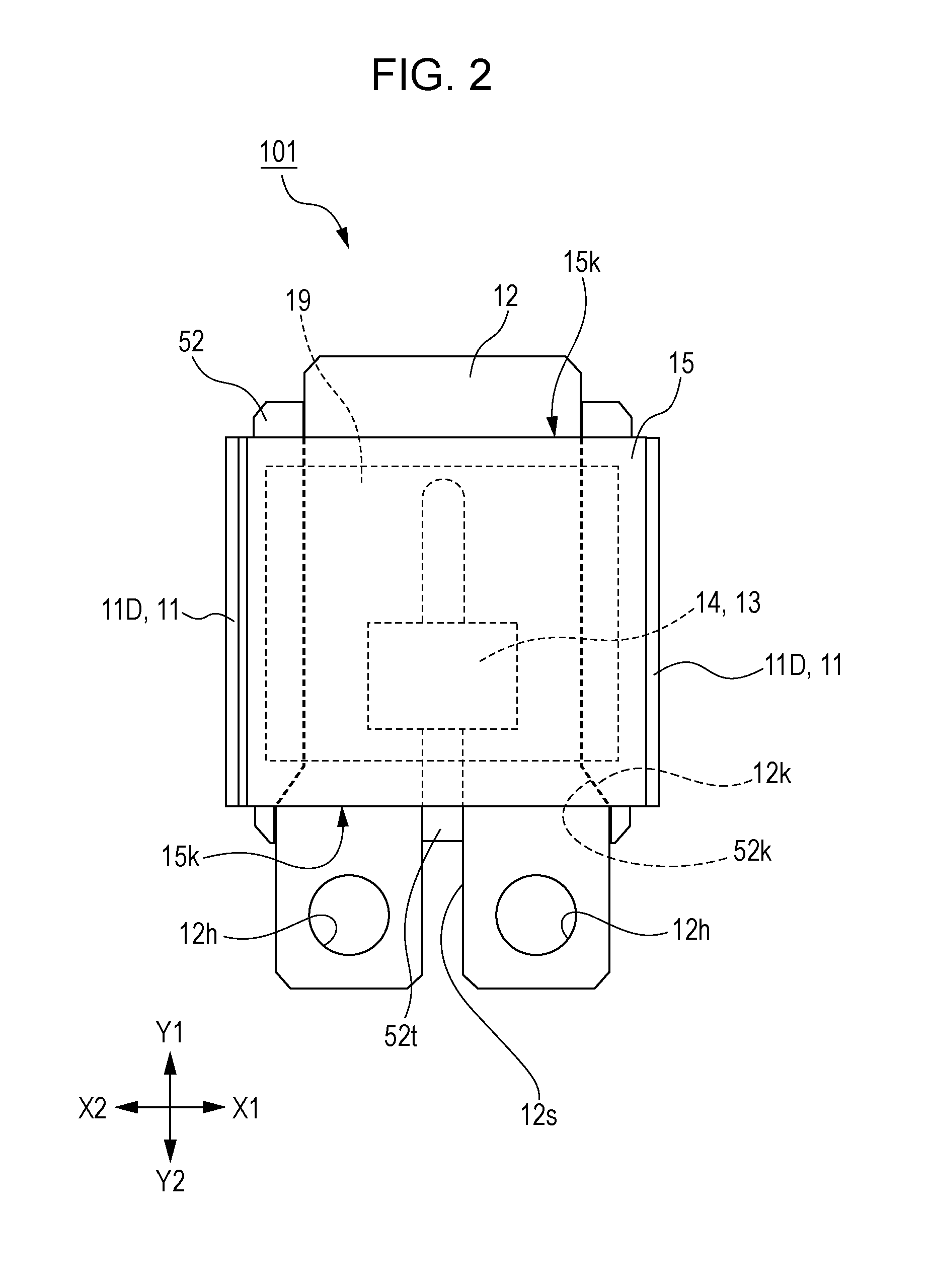
[0044]FIG. 1 is an exploded perspective view explaining a current sensor 101 of a first embodiment of the present invention. FIG. 2 is a diagram explaining the current sensor 101 of the first embodiment of the present invention, and is a top view viewed from a Z1 side illustrated in FIG. 1. In addition, for ease of explanation, an upper case 11A is omitted. FIG. 3 is a diagram explaining the current sensor 101 of the first embodiment of the present invention, and is a top view in which part of a magnetic shielding member 15 and a substrate 19 in FIG. 2 are omitted. FIG. 4 is a configuration diagram explaining the current sensor of the first embodiment of the present invention, and is a plan view illustrating a current path 12 and magnetoelectric conversion elements 13. FIG. 5 is a configuration diagram explaining the current sensor of the first embodiment of the present invention, and is a diagram schematically illustrating a bridge circuit in FIG. 4. FIG. 6 is a configuration diagr...

second embodiment

[0082]FIG. 8 is an exploded perspective view explaining a current sensor 102 of a second embodiment of the present invention. FIG. 9 is a diagram explaining the current sensor 102 of the second embodiment of the present invention, and is a top view viewed from a Z1 side illustrated in FIG. 8. In addition, for ease of explanation, a magnetic shielding member 25A is omitted. FIG. 10 is a diagram explaining the current sensor 102 of the second embodiment of the present invention, and is a top view in which a substrate 29 in FIG. 9 is omitted. FIG. 11 is a configuration diagram explaining the current sensor of the second embodiment of the present invention, and is a plan view illustrating a current path 22 and magnetoelectric conversion elements 23. FIG. 12 is a configuration diagram explaining the current sensor of the second embodiment of the present invention, and is a diagram schematically illustrating a bridge circuit in FIG. 11. FIG. 13 is a configuration diagram explaining the cu...

first example

of Modification

[0099]While the above-mentioned first embodiment adopts a configuration in which the four magnetoelectric conversion elements 13 are put into one package, the first magnetoelectric conversion element 13A and the second magnetoelectric conversion element 13B may be put into one package to form a magnetic sensor package C14A and the third magnetoelectric conversion element 13C and the fourth magnetoelectric conversion element 13D may be put into one package to form a magnetic sensor package C14C, as illustrated in FIG. 14.


PUM


Abstract

A current sensor includes a folded-shaped current path including a pair of arm portions extending in parallel with each other, and a pair of magnetoelectric conversion elements provided so as to sandwich therebetween a symmetric axis passing between the pair of arm portions, the pair of magnetoelectric conversion elements being used for detecting magnetism caused by a current passing through the pair of arm portions, wherein a half-bridge circuit in which the pair of magnetoelectric conversion elements is series-connected and a signal is able to be extracted from a connection point between the pair of magnetoelectric conversion elements is formed, and sensitivity axes of the pair of magnetoelectric conversion elements are oriented in a same direction and sensitivity-influencing axes of the pair of magnetoelectric conversion elements are oriented in a same direction.

Description

CLAIM OF PRIORITY[0001]This application is a Continuation of International Application No. PCT / JP2013 / 060442 filed on Apr. 5, 2013, which claims benefit of Japanese Patent Application No. 2012-114812 filed on May 18, 2012 and No. 2012-152634 filed on Jul. 6, 2012. The entire contents of each application noted above are hereby incorporated by reference.BACKGROUND OF THE INVENTION[0002]1. Field of the Invention[0003]The present invention relates to a current sensor that detects a current flowing through a current path, and in particular, relates to a current sensor that detects magnetism generated when a current flows through a current path having a U-like shape.[0004]2. Description of the Related Art[0005]There have been well known current sensors that are each subsequently attached to an existing current path so as to control or monitor various types of device. It has been well known that, as the current sensor of this type, a magnetic sensor utilizing a magnetoelectric conversion e...

Claims


Application Information

Patent Timeline
IPC IPC(8): G01R33/09G01R15/20G01R19/00G01R33/07
CPCG01R19/0092G01R15/20G01R33/09G01R33/07G01R1/18G01R15/207
Inventor HEBIGUCHI, HIROYUKISATO, ISAO
Owner ALPS ALPINE CO LTD
Why Eureka
Try Eureka