
Zoom lens and imaging apparatus

Active Publication Date: 2015-01-22
FUJIFILM CORP
View PDF1 Cites 12 Cited by
  • Summary
  • Abstract
  • Description
  • Claims
  • Application Information

AI Technical Summary

Benefits of technology

The present invention provides a zoom lens with a constant F-number during magnification change, leading to higher performance and lighter weight. The lens achieves this by using a specific second lens group with negative and positive refractive power that changes distance during magnification change to correct aberration fluctuations. The third lens group is moved in a way that reduces the refractive power of the second lens group at the telephoto end, suppressing fluctuations caused by magnification change. Additionally, a conditional formula is satisfied to further reduce the fluctuations. The imaging apparatus using this zoom lens is small in size and has high performance, with excellent image quality.

Problems solved by technology

However, in all of the zoom lenses disclosed in Patent Documents 1 through 4, despite their image size that is not very large, it is difficult to say that the size of the first lens group is sufficiently reduced.

Method used


Image

  • Zoom lens and imaging apparatus
  • Zoom lens and imaging apparatus
  • Zoom lens and imaging apparatus

Examples


example 1

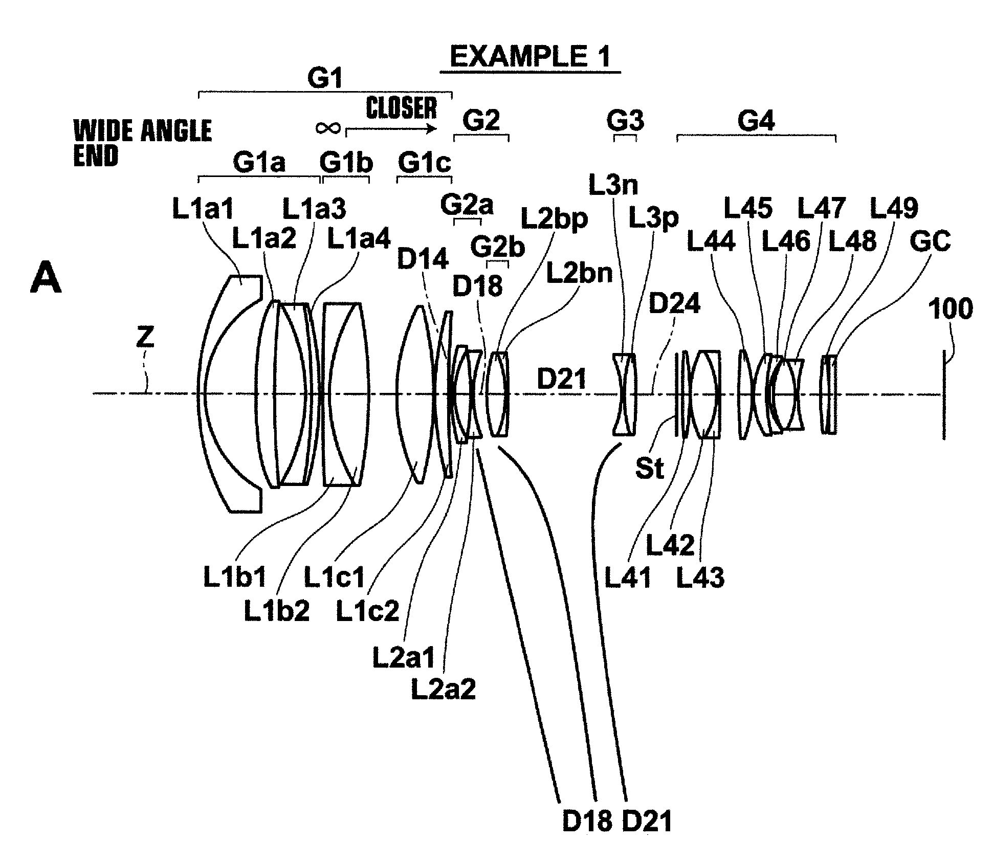
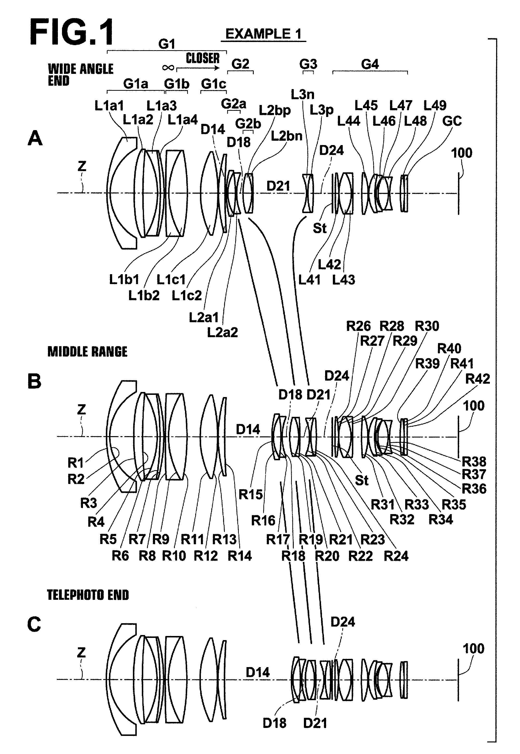
[0106]FIG. 1, Sections A, B and C are diagrams illustrating the structure of the zoom lens in Example 1 of the present invention.

[0107]First lens group G1 of the zoom lens in Example 1 substantially consists of 1a-th lens group G1a having negative refractive power, and which is fixed during focusing, 1b-th lens group G1b having positive refractive power, and which moves during focusing, and 1c-th lens group G1c having positive refractive power, and which is fixed during focusing, in this order from the object side.

[0108]Further, 1a-th lens group G1a substantially consists of 1a1-st lens L1a1 having a negative meniscus lens shape with its convex surface facing the object side, 1a2-nd lens L1a2 having positive refractive power, and a convex surface of which faces the object side, and the absolute value of the curvature radius of the convex surface of 1a2-nd lens L1a2 being smaller than the absolute value of the curvature radius of the other surface of 1a2-nd lens L1a2, and a cemented ...

examples 2 and 3

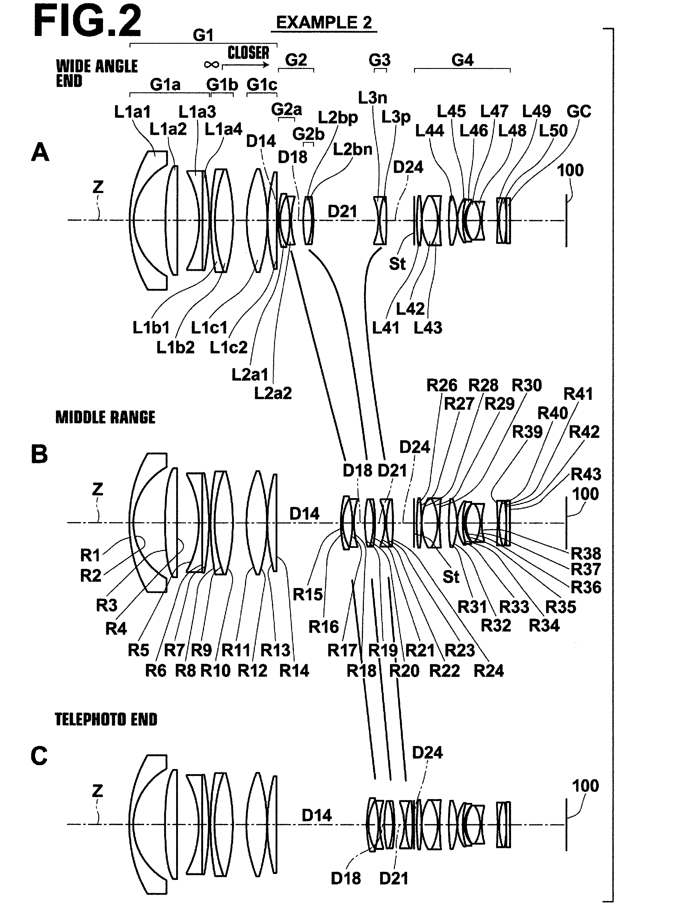
[0124]FIG. 2, Sections A, B and C are diagrams illustrating the structure of the zoom lens in Example 2 of the present invention. FIG. 3, Sections A, B and C are diagrams illustrating the structure of the zoom lens in Example 3 of the present invention. The zoom lenses in Examples 2 and 3 are structured substantially in a similar manner to the zoom lens in Example 1. However, a lens closest to an image plane in fourth lens group G4 is different from Example 1. Instead of 4-9th lens L49, which has positive refractive power, a cemented lens of 4-9th lens L49 having negative refractive power and 4-10th lens L50 having positive refractive power is used. Consequently, surface numbers of lenses located toward the image side of 4-8th lens L48 are shifted by 1 from those of Example 1.

[0125]Tables 4 through 6 show specific lens data of the zoom lens in Example 2 in a similar manner to Example 1, as described above. Further, Tables 7 through 9 show specific lens data of the zoom lens in Examp...


PUM


Abstract

A zoom-lens substantially consists of a positive-first-lens-group, fixed during magnification-change, a negative-second-lens-group, which moves from object-side toward image-side during magnification change from wide-angle-end to telephoto-end, a negative-third-lens-group, which corrects movement of an image-plane during magnification-change, and a positive-fourth-lens-group, which is fixed during magnification-change and includes a stop, in this order from object-side. The first-lens-group substantially consists of a negative-1a-th-lens-group, fixed during focusing, a positive-1b-th-lens-group, which moves during focusing, and a positive-1c-th-lens-group, fixed during focusing, in this order from object-side. The second-lens-group substantially consists of a negative-2a-th-lens-group and a positive-2b-th-lens-group, and a distance therebetween is changed during magnification-change. The third-lens-group moves in such a manner that a distance from the fourth-lens-group at telephoto-end is narrower than a distance from the fourth-lens-group at wide-angle-end. Predetermined conditional-formulas about a length from a most-object-side surface in the first-lens-group to the stop, a focal-length at wide-angle-end and a focal-length of the 1b-th-lens-group are satisfied.

Description

CROSS-REFERENCE TO RELATED APPLICATIONS[0001]This application is a Continuation of PCT International Application No. PCT / JP2013 / 002356 filed on Apr. 5, 2013, which claims priority under 35 U.S.C. §119(a) to Japanese Patent Application No. 2012-088064 filed on Apr. 9, 2012. Each of the above applications is hereby expressly incorporated by reference, in its entirety, into the present application.BACKGROUND OF THE INVENTION[0002]1. Field of the Invention[0003]The present invention relates to a zoom lens used in an electronic camera, such as a digital camera, a video camera, a camera for broadcasting, a camera for movies and a camera for surveillance, and also to an imaging apparatus on which the zoom lens is mounted.[0004]2. Description of the Related Art[0005]In electronic cameras, such as a camera for broadcasting and a camera for film-making, a fluctuation of an angle of view caused by focusing is not desirable. Therefore, as a zoom lens consisting of four lens groups of a first th...

Claims


Application Information

Patent Timeline
IPC IPC(8): G02B15/14G02B13/18
CPCG02B13/18G02B15/14G02B15/173G02B27/646G02B15/144109
Inventor KOMATSU, DAIKICHO, MICHIO
Owner FUJIFILM CORP
Learn More