System for providing fuel to a combustor

a technology of combustor and fuel supply, which is applied in the direction of turbine/propulsion fuel heating, machines/engines, lighting and heating apparatus, etc., can solve the problems of labor-intensive, difficult fuel connection between the fuel source and the late lean fuel injector, and restricted access to the various fluid couplings

Inactive Publication Date: 2015-01-29
GENERAL ELECTRIC CO
View PDF3 Cites 19 Cited by
  • Summary
  • Abstract
  • Description
  • Claims
  • Application Information

AI Technical Summary

Problems solved by technology

Access to the various fluid couplings, fluid conduits and/or the late lean fuel injectors may be restricted during installation and/or removal of the combustor due to limited spa

Method used


Image

  • System for providing fuel to a combustor
  • System for providing fuel to a combustor
  • System for providing fuel to a combustor

Examples


Embodiment Construction

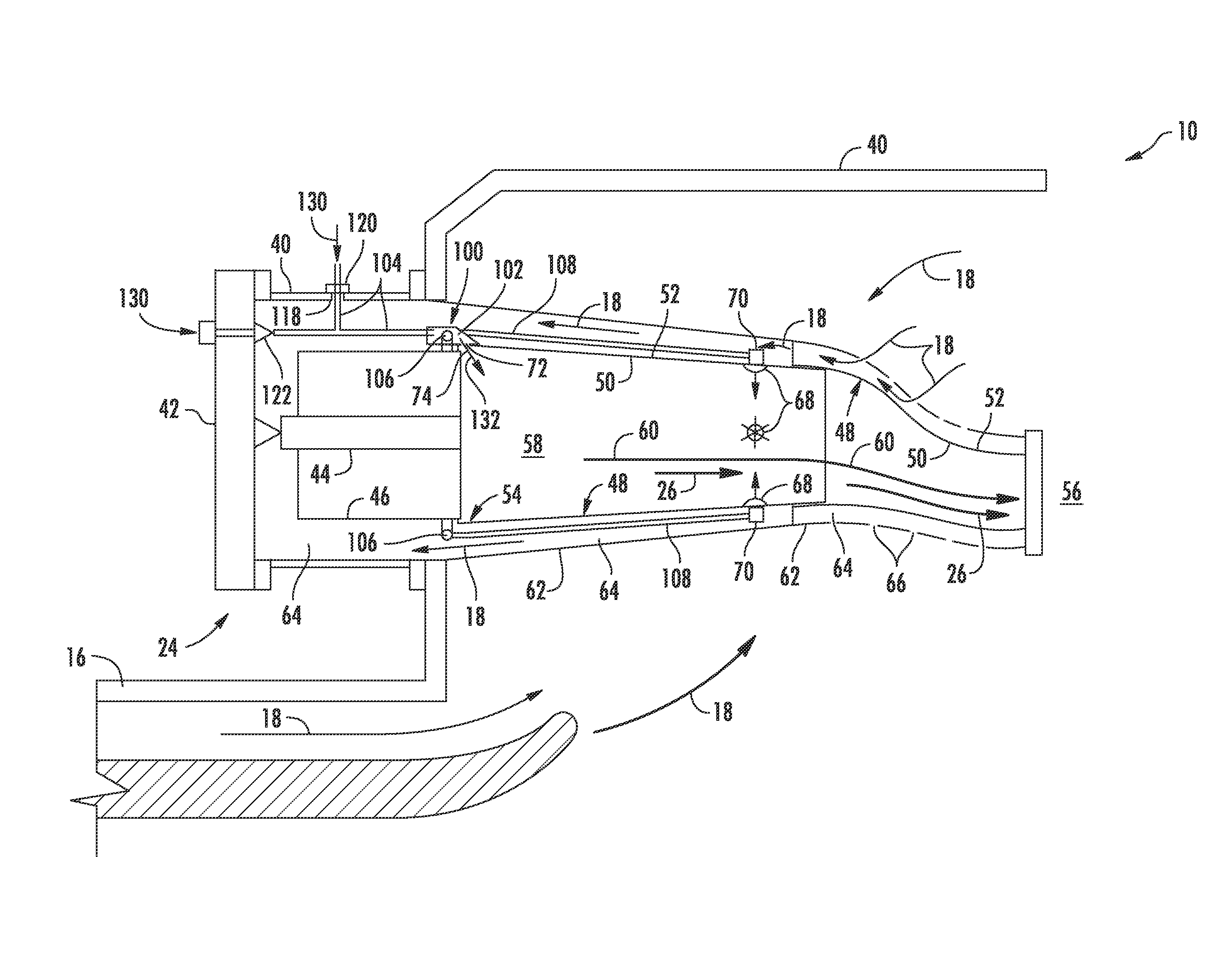
[0019]Reference will now be made in detail to present embodiments of the invention, one or more examples of which are illustrated in the accompanying drawings. The detailed description uses numerical and letter designations to refer to features in the drawings. Like or similar designations in the drawings and description have been used to refer to like or similar parts of the invention. As used herein, the terms “first”, “second”, and “third” may be used interchangeably to distinguish one component from another and are not intended to signify location or importance of the individual components. The terms “upstream” and “downstream” refer to the relative direction with respect to fluid flow in a fluid pathway. For example, “upstream” refers to the direction from which the fluid flows, and “downstream” refers to the direction to which the fluid flows. The term “radially” refers to the relative direction that is substantially perpendicular to an axial centerline of a particular compone...


PUM


Abstract

A fuel supply system for a gas turbine combustor includes an annular duct that at least partially defines a hot gas path within the combustor. An orifice is at least partially defined by the annular duct and defines a flow path through the annular duct into the hot gas path. A plurality of fuel injectors are arranged circumferentially around the annular duct to provide for fluid communication through the annular duct into the hot gas path. A fuel distribution manifold is disposed adjacent to an outer side of the annular duct. The fuel distribution manifold includes a main body that at least partially defines an inlet for receiving fuel, an outlet that is in fluid communication with the fuel injectors, and a fuel purge passage that provides for fluid communication between the inlet and the orifice.

Description

FEDERAL RESEARCH STATEMENT[0001]This invention was made with Government support under Contract No. DE-FC26-05NT42643, awarded by the Department of Energy. The Government has certain rights in the invention.FIELD OF THE INVENTION[0002]The present invention generally involves a combustor of a gas turbine. More specifically, the invention relates to a system for providing fuel to a fuel injector disposed downstream from a primary combustion zone defined within the combustor.BACKGROUND OF THE INVENTION[0003]Combustors are commonly used in industrial and power generation operations to ignite fuel to produce combustion gases having a high temperature and pressure. For example, turbomachines such as gas turbines typically include one or more combustors to generate power or thrust. A typical gas turbine includes an inlet section, a compressor section, a combustion section, a turbine section, and an exhaust section. The inlet section cleans and conditions a working fluid (e.g., air) and supp...

Claims


Application Information

Patent Timeline
IPC IPC(8): F02C7/22F23R3/28
CPCF23R3/28F02C7/222F02C7/224F23R3/34F23R3/346
Inventor BERRY, JONATHAN DWIGHT
Owner GENERAL ELECTRIC CO
Why Eureka
Try Eureka