

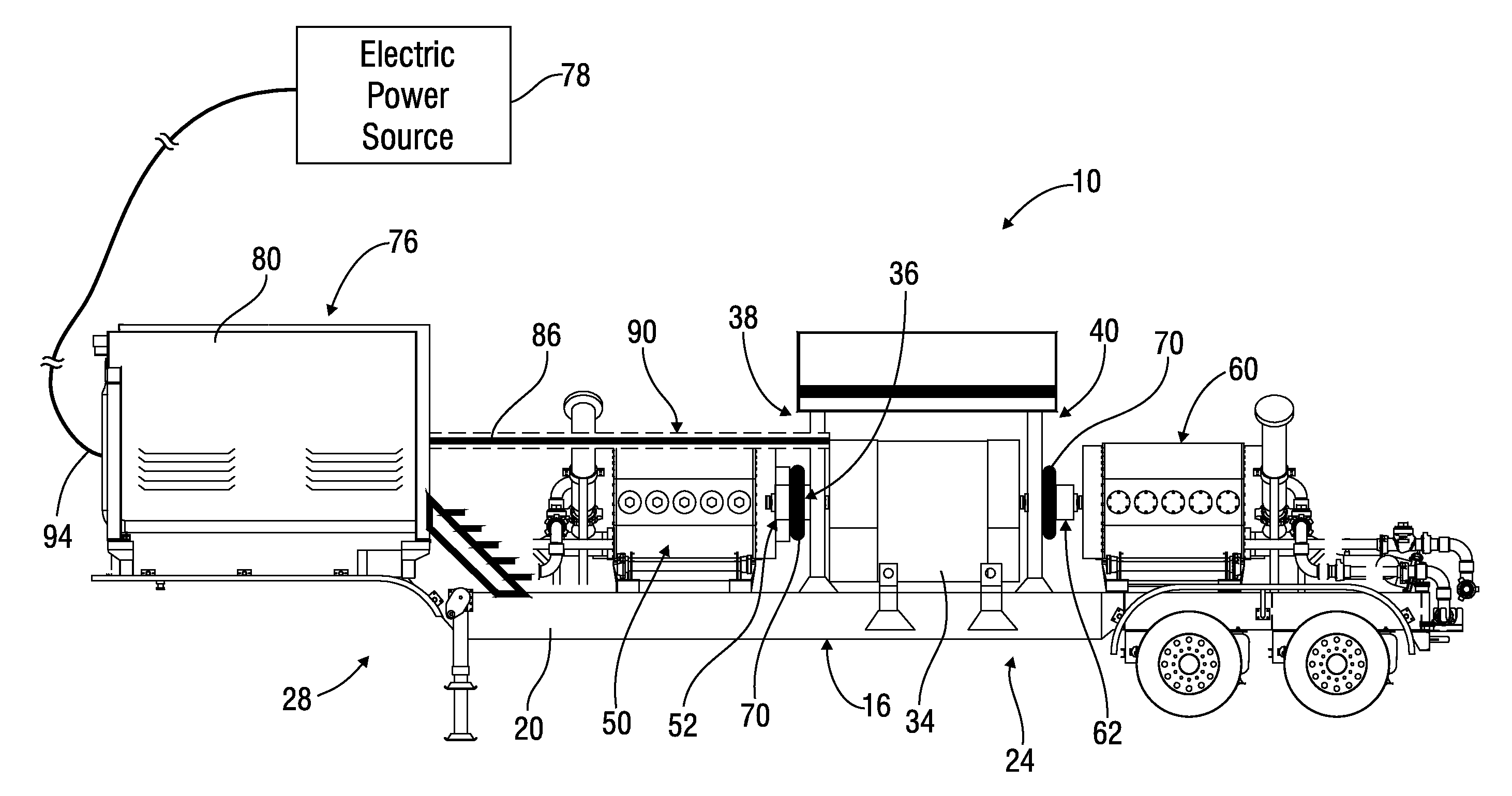
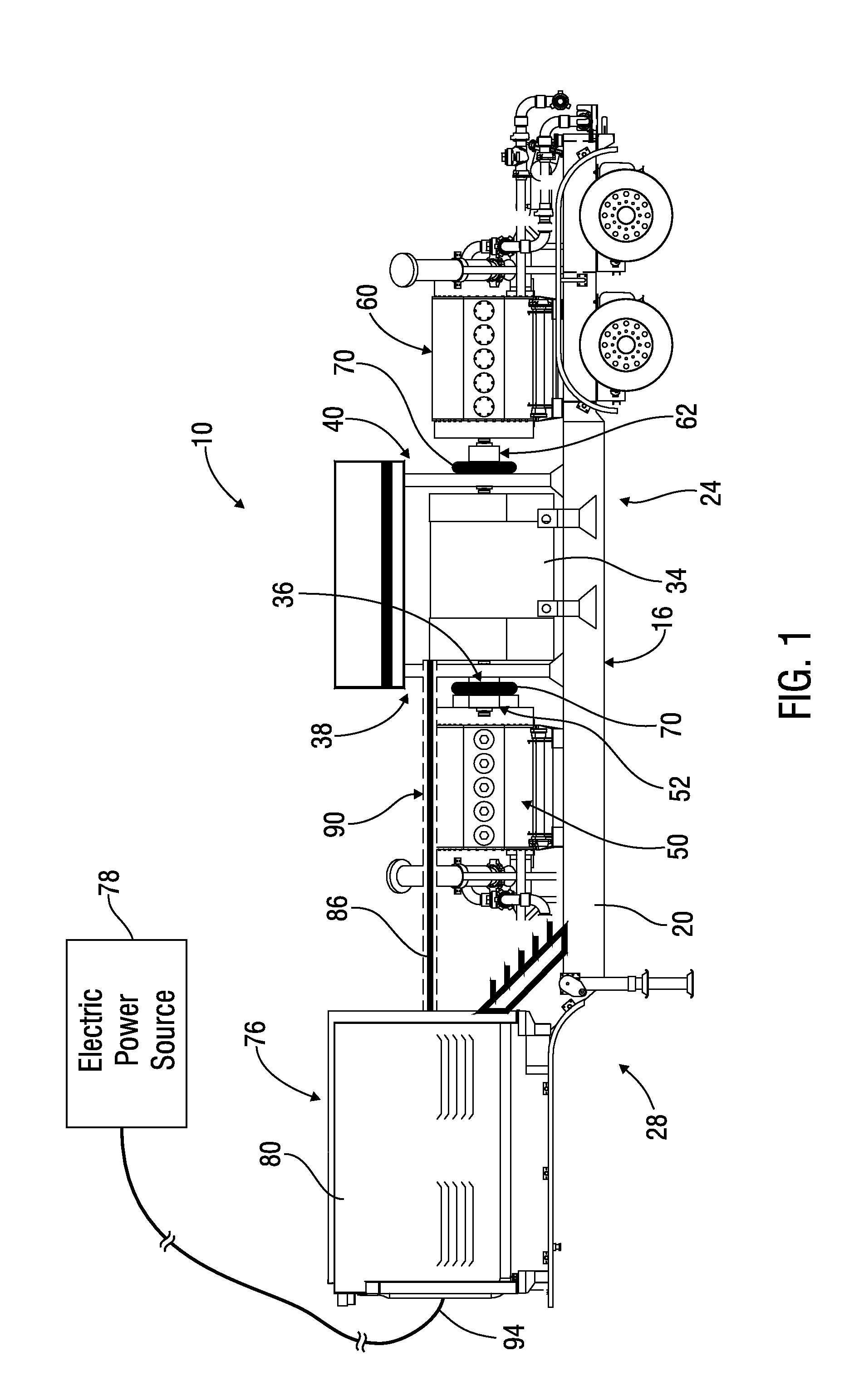
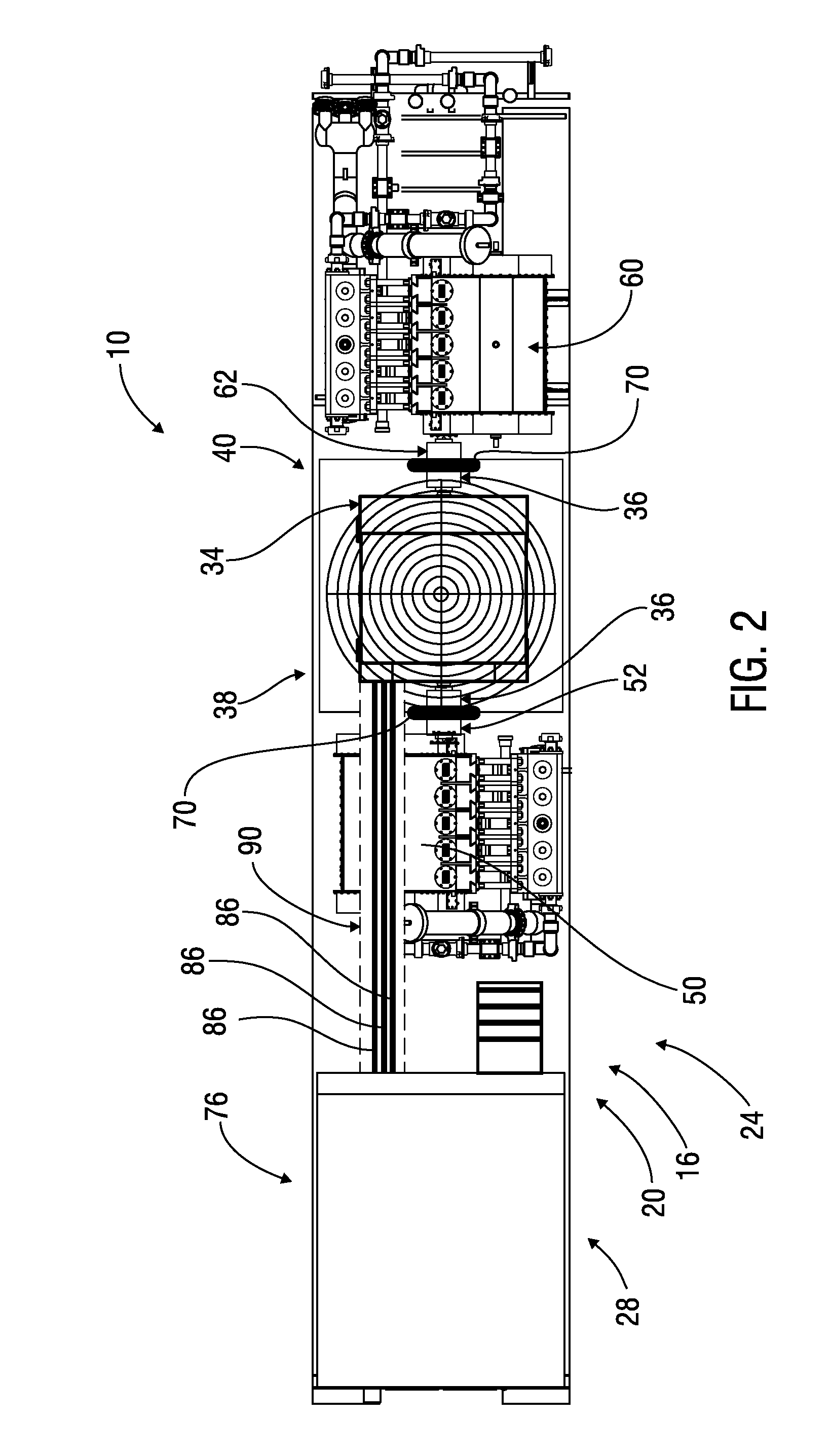
Apparatus and methods for delivering a high volume of fluid into an underground well bore from a mobile pumping unit
a mobile pumping unit and high-volume technology, applied in the direction of tank vehicles, borehole/well accessories, transportation items, etc., can solve the problems of increasing the number of drivers and operators needed and personnel on site, increasing the cost of operations and the potential for safety-related incidents, and limiting the number of other important equipmen
- Summary
- Abstract
- Description
- Claims
- Application Information
AI Technical Summary
Benefits of technology
Problems solved by technology
Method used
Image

Examples
Embodiment Construction
[0015]Characteristics and advantages of the present disclosure and additional features and benefits will be readily apparent to those skilled in the art upon consideration of the following detailed description of exemplary embodiments of the present disclosure and referring to the accompanying figures. It should be understood that the description herein and appended drawings, being of example embodiments, are not intended to limit the claims of this patent or any patent claiming priority hereto. On the contrary, the intention is to cover all modifications, equivalents and alternatives falling within the spirit and scope of the claims. Many changes may be made to the particular embodiments and details disclosed herein without departing from such spirit and scope.
[0016]In showing and describing preferred embodiments in the appended figures, common or similar elements are referenced with like or identical reference numerals or are apparent from the figures and / or the description herein...
PUM
 Abstract
Description
Claims
Application Information