Helicopter rotor load reduction and tip clearance control

a technology of rotor load reduction and tip clearance control, which is applied in the direction of propellers, aircrafts, transportation and packaging, etc., can solve the problem that the control of the 2/rev blade typically cannot be accomplished using an ordinary swashplate, and achieve the effect of reducing the vibratory load of the blad

Active Publication Date: 2015-01-29
SIKORSKY AIRCRAFT CORP
View PDF2 Cites 47 Cited by
  • Summary
  • Abstract
  • Description
  • Claims
  • Application Information

AI Technical Summary

Problems solved by technology

2 / rev blade control typically cannot be accomplished using an ordinary swashplate, at least for rotors with two blades or more than three blades.

Method used


Image

  • Helicopter rotor load reduction and tip clearance control
  • Helicopter rotor load reduction and tip clearance control
  • Helicopter rotor load reduction and tip clearance control

Examples


Embodiment Construction

[0015]It is noted that various connections are set forth between elements in the following description and in the drawings (the contents of which are included in this disclosure by way of reference). It is noted that these connections in general and, unless specified otherwise, may be direct or indirect and that this specification is not intended to be limiting in this respect. In this respect, a coupling between entities may refer to either a direct or an indirect connection.

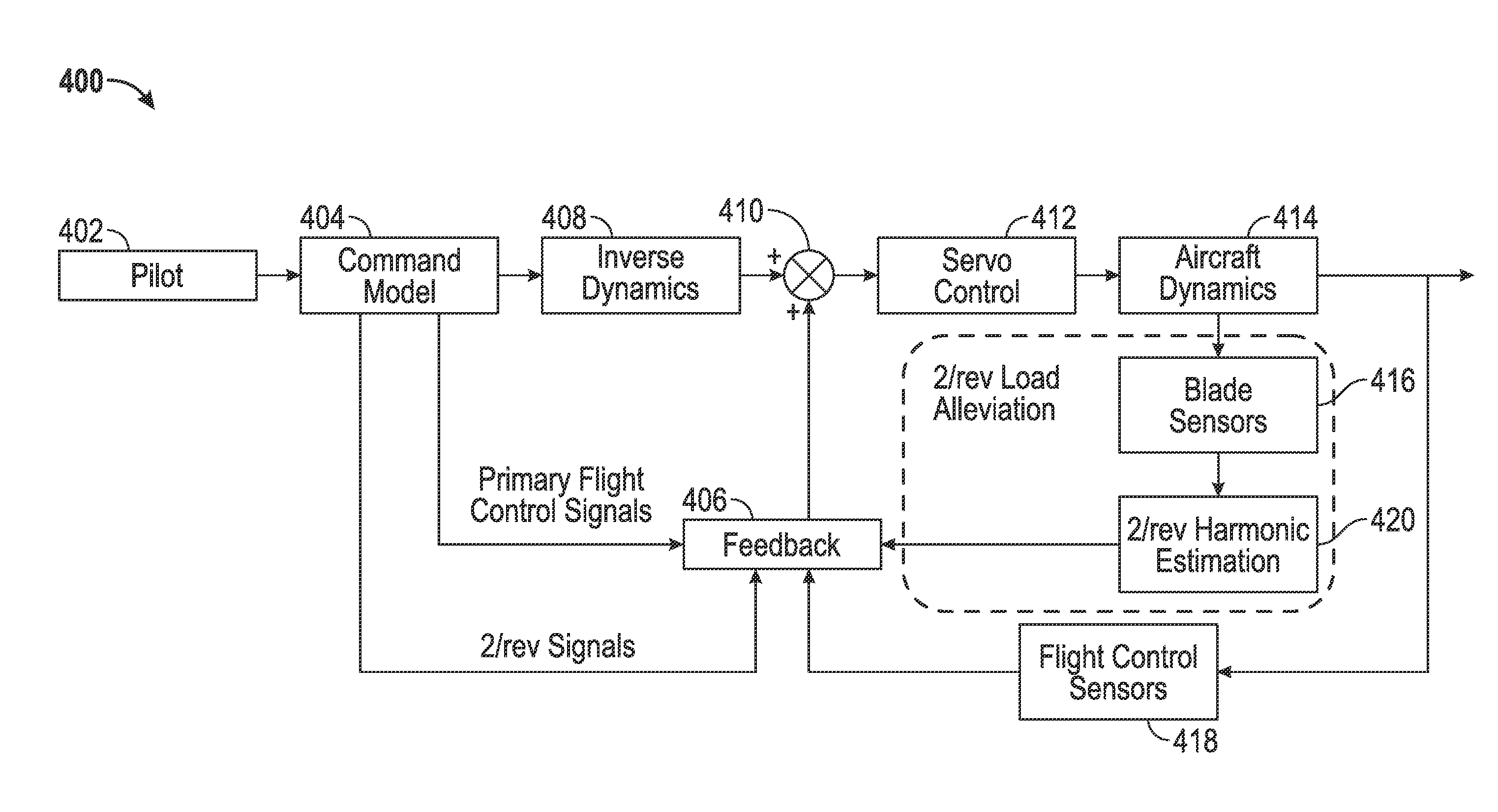
[0016]Exemplary embodiments of apparatuses, systems, and methods are described for using 2 / rev individual blade control (IBC) feedback to reduce 2 / rev blade deflections and loads. In some embodiments, one or more blade sensors may detect 2 / rev bending signals. The signals may be processed and actions may be taken to null or mitigate the impact of the 2 / rev loads. In some embodiments, a controller may convert from commands for lateral, longitudinal, and / or collective blade cyclic pitch (A1s, B1s, Theta) to posit...


PUM


Abstract

A method of controlling a helicopter having a rotor with blades is provided. The method includes receiving, by a computing device comprising a processor, at least one input associated with the helicopter; generating, by the computing device, control signals configured to counteract blade bending associated with the rotors based on the received at least one input; measuring, by the computing device, blade signals using sensors for the blades; extracting, by the computing device, harmonic loads from the measured blade signals; adapting, by the computing device, the control signals based on the harmonic loads; and controlling, by the computing device, servos connected to the blades to adjust the blades according to the adapted control signals to reduce vibratory loads on the blades.

Description

BACKGROUND[0001]Total vehicle height is an important design parameter for fitting on existing ship hangers and elevators, as well as fitting inside transport aircraft. As shown in FIGS. 1 and 2A-2B, conventional coaxial helicopters are typically taller than other helicopters of similar performance due to the existence of an additional rotor and the flapping motion of the rotor blades necessitating a minimum vertical hub spacing (rotor separation ratio). In particular, FIG. 1 shows an upper rotor 102 coupled to an upper rotor swashplate 104 and a lower rotor 106 coupled to a lower rotor swashplate 108. A rotor hub separation 110 may generally separate the upper rotor 102 and lower rotor 106. FIG. 2A illustrates a single axis / rotor helicopter 202, whereas FIG. 2B illustrates a coaxial / dual rotor helicopter 204. As shown in FIGS. 2A-2B, the height of the helicopter 204 may be appreciably greater than the height of the helicopter 202.[0002]Some helicopters, such as the Sikorsky X2 Techn...

Claims


Application Information

Patent Timeline
Patent Type & Authority Applications(United States)
IPC IPC(8): B64C27/00B64C27/04B64C19/00
CPCB64C27/001B64C27/04B64C19/00B64C27/008B64C27/10B64C2027/002B64C2027/7238Y02T50/30
Inventor ELLER, EREZKNAG, JOHN
Owner SIKORSKY AIRCRAFT CORP
Why Eureka
Try Eureka