
Mounting system for sealing and aligning the burner of the lamp at the centre of its base

a technology of mounting system and burner, which is applied in the direction of discharge tube/lamp details, electric discharge lamps, electrical apparatus, etc., can solve the problems of large air bubbles in hardened cement, lamp base loosening, and cement can start crumbling, and achieve the effect of convenient insertion of burners

Inactive Publication Date: 2015-01-29
FLOWIL INT LIGHTING HLDG BV
View PDF5 Cites 9 Cited by
  • Summary
  • Abstract
  • Description
  • Claims
  • Application Information

AI Technical Summary

Benefits of technology

The present invention provides a solution to several technical problems such as electrical short circuits, cementless bases for lamps, and mechanical bases for lamps with a specially designed spring clip. The clip allows for easy insertion and locking of the burner into the base and keeps it aligned in both horizontal and longitudinal directions. The cementless base can also be used for single ended lamps with only one lead wire coming out of the pinch of the bulb. Overall, the invention improves the performance and reliability of lamps.

Problems solved by technology

In case of flawed formulation, the cement can start crumbling and the lamp will become loose at the base.
In case said process is done hastily, the suspension can “boil”, leaving larger air bubbles in the hardened cement.
Applying the cement is a time consuming process as one needs to prepare the mixture, apply the suspension to the base of the lamp while burner is inside the base, allow the cement to dry and also clean the spilt cement from the lamp and also clean the used tools before cement hardens.
In this patent differently designed clip is being used inside the base with the objective of electrically connecting the burner and hence there is a risk of electrical breakdown when high voltage is used as for discharge lamps.
If the positioning is not good, the burner can be out of line because it is only held on the bottom in the base and the positioning in horizontal or longitudinal direction in the base is not under control.
Thus, the conventional system does not provide proper alignment of the lamp in the center of the base.
Also, the conventional clips cannot be used for lamps where position of the burner is more critical e.g. photo-optic lamps.

Method used


Image

  • Mounting system for sealing and aligning the burner of the lamp at the centre of its base
  • Mounting system for sealing and aligning the burner of the lamp at the centre of its base
  • Mounting system for sealing and aligning the burner of the lamp at the centre of its base

Examples


Embodiment Construction

[0026]The embodiments of the present disclosure will now be described in detail with reference to the accompanying drawings. However, the present disclosure is not limited to the embodiments. The present disclosure can be modified in various forms. Thus, the embodiments of the present disclosure are only provided to explain more clearly the present disclosure to the ordinarily skilled in the art of the present disclosure. In the accompanying drawings, like reference numerals are used to indicate like components.

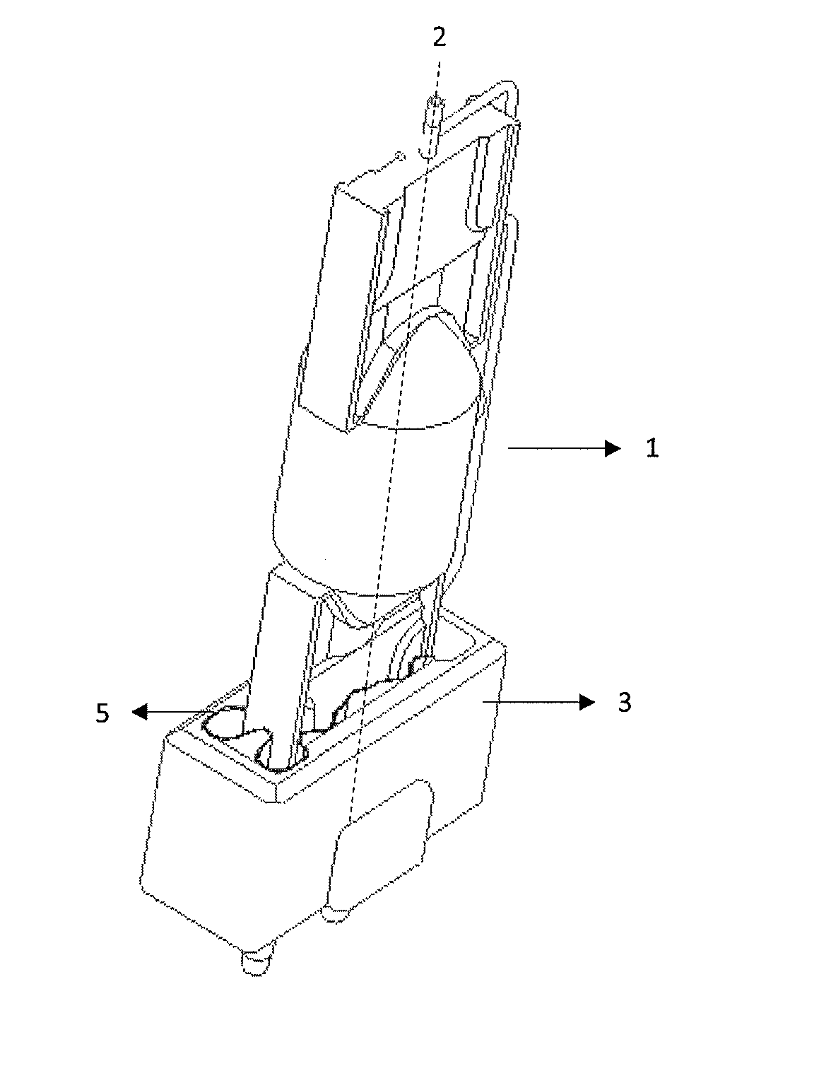
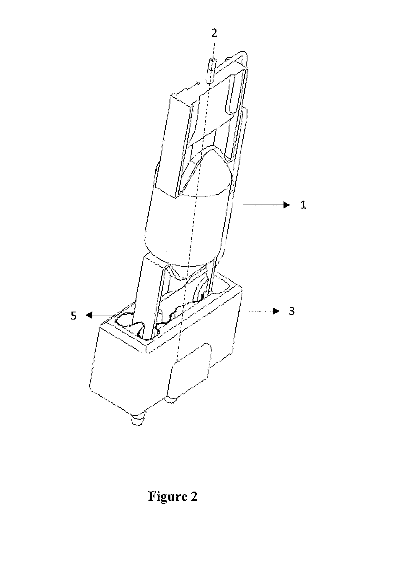
[0027]Reference may be made to FIG. 2 which shows the lamp (1) with the cement less base (3), according to an embodiment of the present disclosure. The lamp (1) is provided with or without an outer bulb, which has a longitudinal axis (2). The burner of the lamp is sealed or pinched at one end which has at least one supply lead (4) guided outward on the end. The base (3) is in the form of a trough-shaped holder to hold the contact points of supply lead (4) protruding from the ...


PUM


Abstract

A lamp having a longitudinal axis, comprising of a burner pinched at one end and a cement less base holding the contact points protruding from the burner. At least one end of the burner is sealed and aligned at the centre of the base in an upright direction following the lamp axis by means of a spring clip, which is mounted from the side of the pinch of the burner and does not interfere with the lead wires.

Description

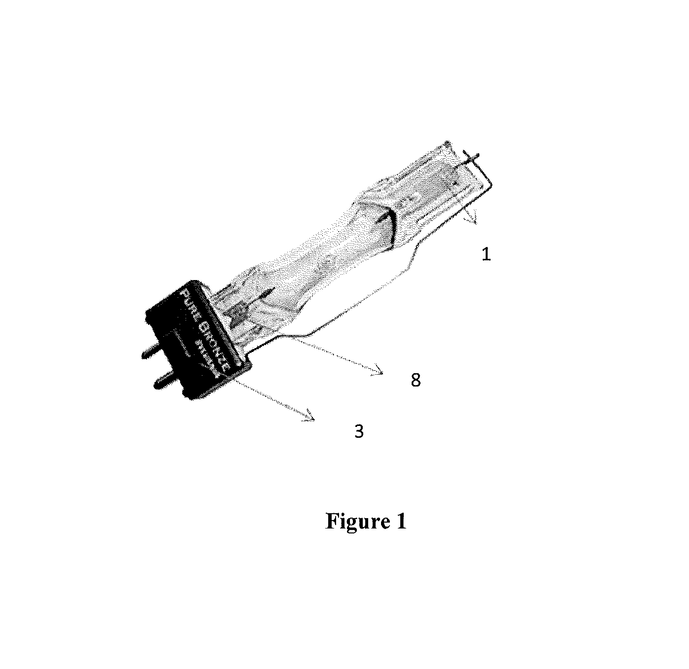
FIELD OF THE INVENTION[0001]The present invention relates in general, to a cement less base for the lamp. More particularly, the present invention provides a cement less base adapted with a spring clip for sealing and aligning the burner of the lamp at the centre of the base.BACKGROUND OF THE INVENTION[0002]Conventionally, in lamp technology, the base of the lamp is attached to the burner by cement. Also referring to FIG. 1 of the accompanying drawings, this ceramic suspension (8) is applied between the lamp base (3) and the burner of the lamp (1). After application, this suspension needs to be dried out (at a higher temperature e.g. 150° C.) to harden it. The formulation of this suspension is critical to have the right strength and stability over the life of the lamp. In case of flawed formulation, the cement can start crumbling and the lamp will become loose at the base.[0003]Also, the heating process to dry and harden the cement is critical for its strength and stability. In case...

Claims


Application Information

Patent Timeline
IPC IPC(8): H01J5/60
CPCH01J5/60H01K1/46H01J5/48
Inventor DERHAEG, LODEBROEDERS, FRANKWILLEMS, MARCHOOKER, JAMESDERWAEL, PETER
Owner FLOWIL INT LIGHTING HLDG BV
Learn More