Apparatus and method for a symmetric sequential entangler of periodic photons in a single input and output mode

a symmetric sequential and periodic photon technology, applied in the field of apparatus and method for a symmetric sequential entanglement of periodic photons in a single input and output mode, can solve the problem of inability to predict the time between two subsequent spontaneous events

Active Publication Date: 2015-01-29
THE UNITED STATES OF AMERICA AS REPRESETNED BY THE SEC OF THE AIR FORCE
View PDF7 Cites 6 Cited by
  • Summary
  • Abstract
  • Description
  • Claims
  • Application Information

AI Technical Summary

Benefits of technology

[0007]The present invention creates the entanglement of sequential qubits by using a unique “loop back” architecture that delays one photon for one period T of the sequence thus allowing for two photons to be acted on by a standard entangling element; which, in the present invention uses the simple polarization encoded CZ gate of Crespi et. al (WO2012150568A1). After the CZ gate one photon (now entangled so which cannot be distinguished) is then released and the second is looped back to coincide with the arrival of the next photon and so on. This will probabilistically produce a linear cluster state. The term probabilistically as th

Problems solved by technology

It is impossible to predict the time be

Method used


Image

  • Apparatus and method for a symmetric sequential entangler of periodic photons in a single input and output mode
  • Apparatus and method for a symmetric sequential entangler of periodic photons in a single input and output mode

Examples


Embodiment Construction

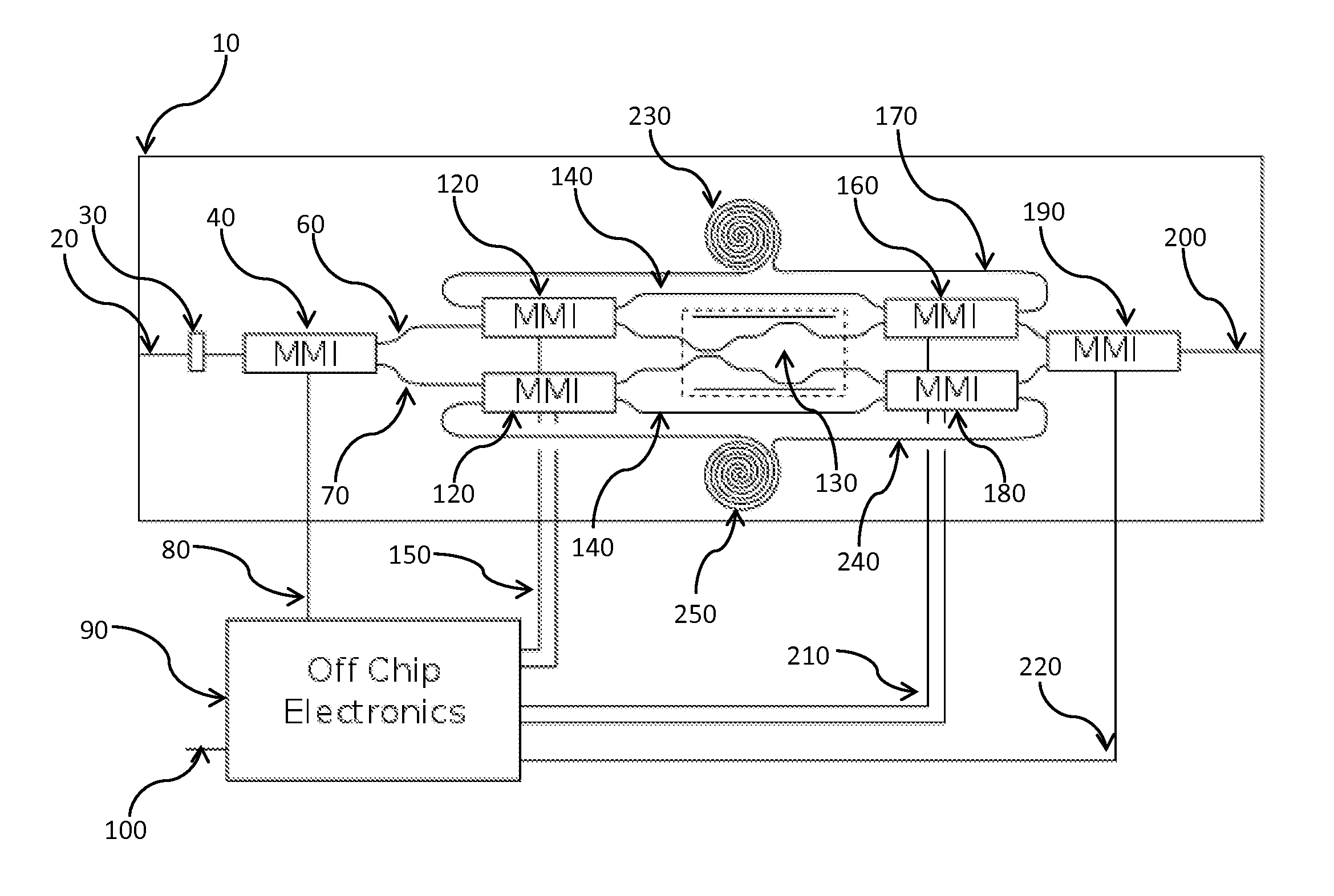
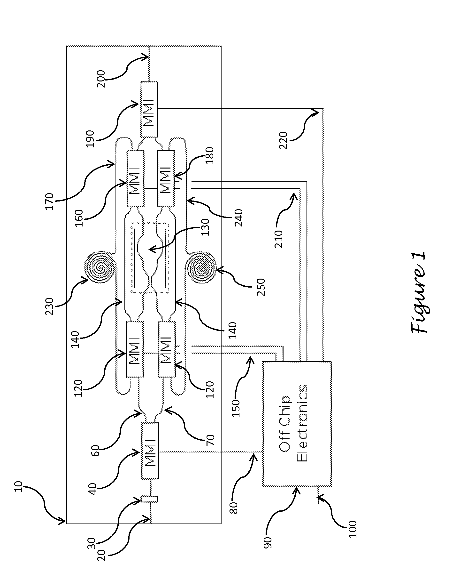
[0010]A sequence of periodic photons created by any means enter the integrated waveguide chip 10 in FIG. 1 via the input port 20. The integrated waveguide may be made from any of a number of materials. In our preferred embodiment we will use Lithium Niobate (LiNbO3) as the waveguide material. The input port 20 is a polarization maintaining optical waveguide fabricated in the LiNbO3 chip 10. Polarization maintaining waveguides are required as we chose to encode our qubits in the polarization modes of each photon. Thus the resource of periodic photons must also be in a known polarization state. It is then trivial to rotate the input state polarization state to any desired state via a polarization controller 30. The preferred embodiment of the present invention uses integrated waveguide based polarization controllers 30 which function via the electro-optical effect. The preferred embodiment of the present invention utilizes the Pockels effect which is innate to lithium niobate. Such ro...


PUM


Abstract

An apparatus providing an integrated waveguide device that creates entanglement between a symmetrical sequence of periodically spaced (in time) photons in a single input and output mode. The invention comprises a polarization maintaining integrated waveguide chip containing a number of delay lines, integrated multimode interferometers with the potential for rapid switching, a polarization controller and off chip computer logic and timing.

Description

PRIORITY CLAIM UNDER 35 U.S.C. §119(e)[0001]This patent application claims the priority benefit of the filing date of provisional application Ser. No. 61 / 857,710, having been filed in the United States Patent and Trademark Office on Jul. 24, 2013 and now incorporated by reference herein.STATEMENT OF GOVERNMENT INTEREST[0002]The invention described herein may be manufactured and used by or for the Government for governmental purposes without the payment of any royalty thereon.BACKGROUND OF THE INVENTION[0003]A cluster state can be loosely defined as an entangled set of qubits arranged in a lattice. Breigel and Raussendorf strictly define a cluster state as “Let each lattice site be specified by a d-tuple of (positive or negative) integers a εZd. Each sight has 2d neighboring sites. If occupied, they interact with the qubit a”. This implies a cluster state has interaction between all nearest neighbor qubits. In one dimension (d=1) this results in a linear chain of qubits, of arbitrary...

Claims


Application Information

Patent Timeline
IPC IPC(8): G06N99/00G02F1/225
CPCG06N99/002Y10S977/933G02F1/225B82Y20/00G02F2201/20G02F1/212G06N10/00H04B10/70H04L9/0852
Inventor SMITH, AMOS M.FANTO, MICHAEL L.
Owner THE UNITED STATES OF AMERICA AS REPRESETNED BY THE SEC OF THE AIR FORCE
Why Eureka
Try Eureka