Light guide plate, surface source device and transmission-type display device

a technology of surface source and light guide plate, which is applied in the direction of planar/plate-like light guide, lighting and heating apparatus, instruments, etc., can solve the problems of low light guide efficiency, low convergence of light and low front luminance, and the inclined surfaces from which light reflects are susceptible to scratching, so as to achieve high in-plane brightness. the effect of uniformity

a technology of surface source and light guide plate, which is applied in the direction of planar/plate-like light guide, lighting and heating apparatus, instruments, etc., can solve the problems of low light guide efficiency, low convergence of light and low front luminance, and the inclined surfaces from which light reflects are susceptible to scratching, so as to achieve high in-plane brightness. the effect of uniformity

US20150029745A1Active Publication Date: 2015-01-29DAI NIPPON PRINTING CO LTD

Image

  • Light guide plate, surface source device and transmission-type display device
  • Light guide plate, surface source device and transmission-type display device
  • Light guide plate, surface source device and transmission-type display device

Examples


embodiment

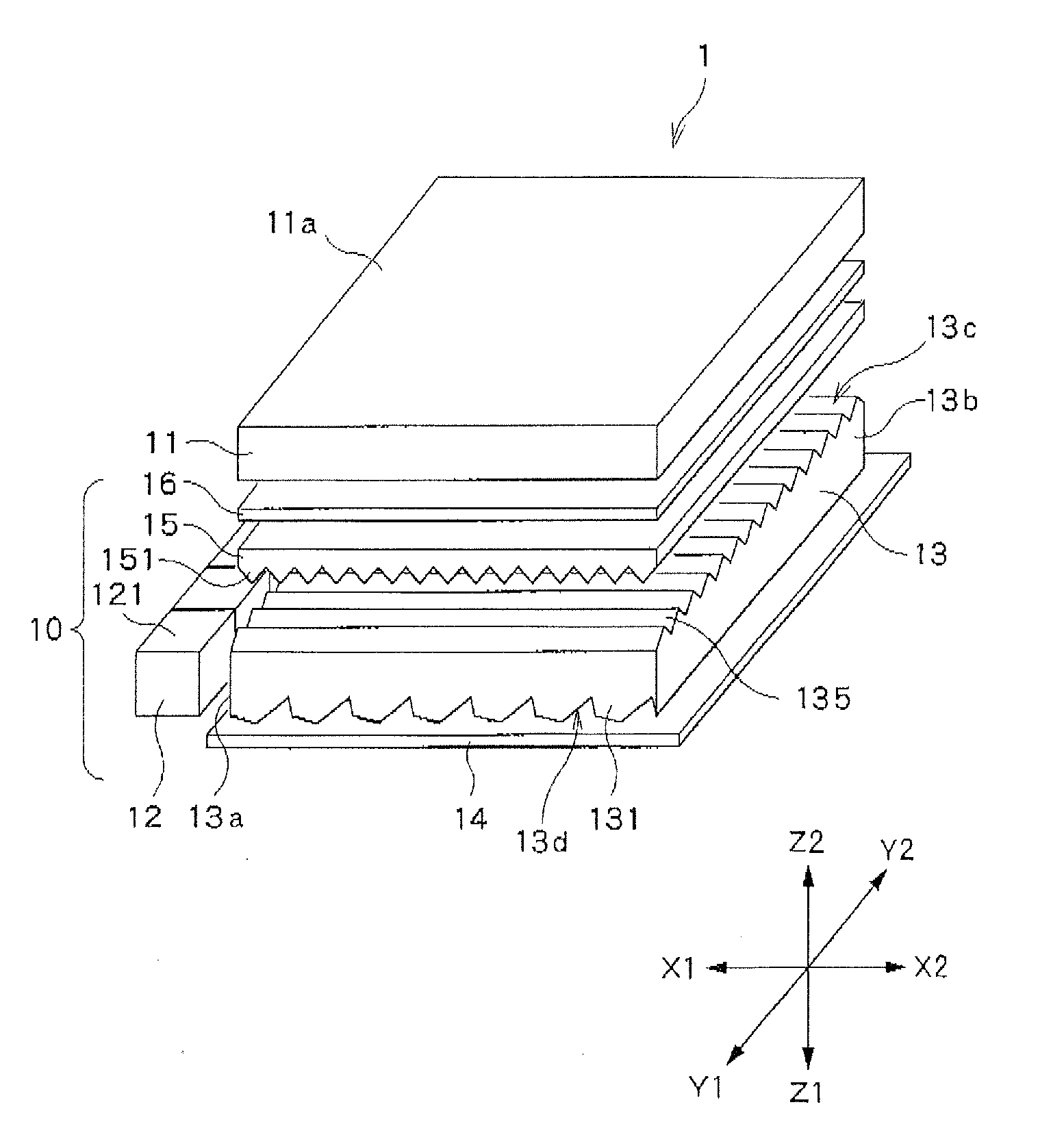
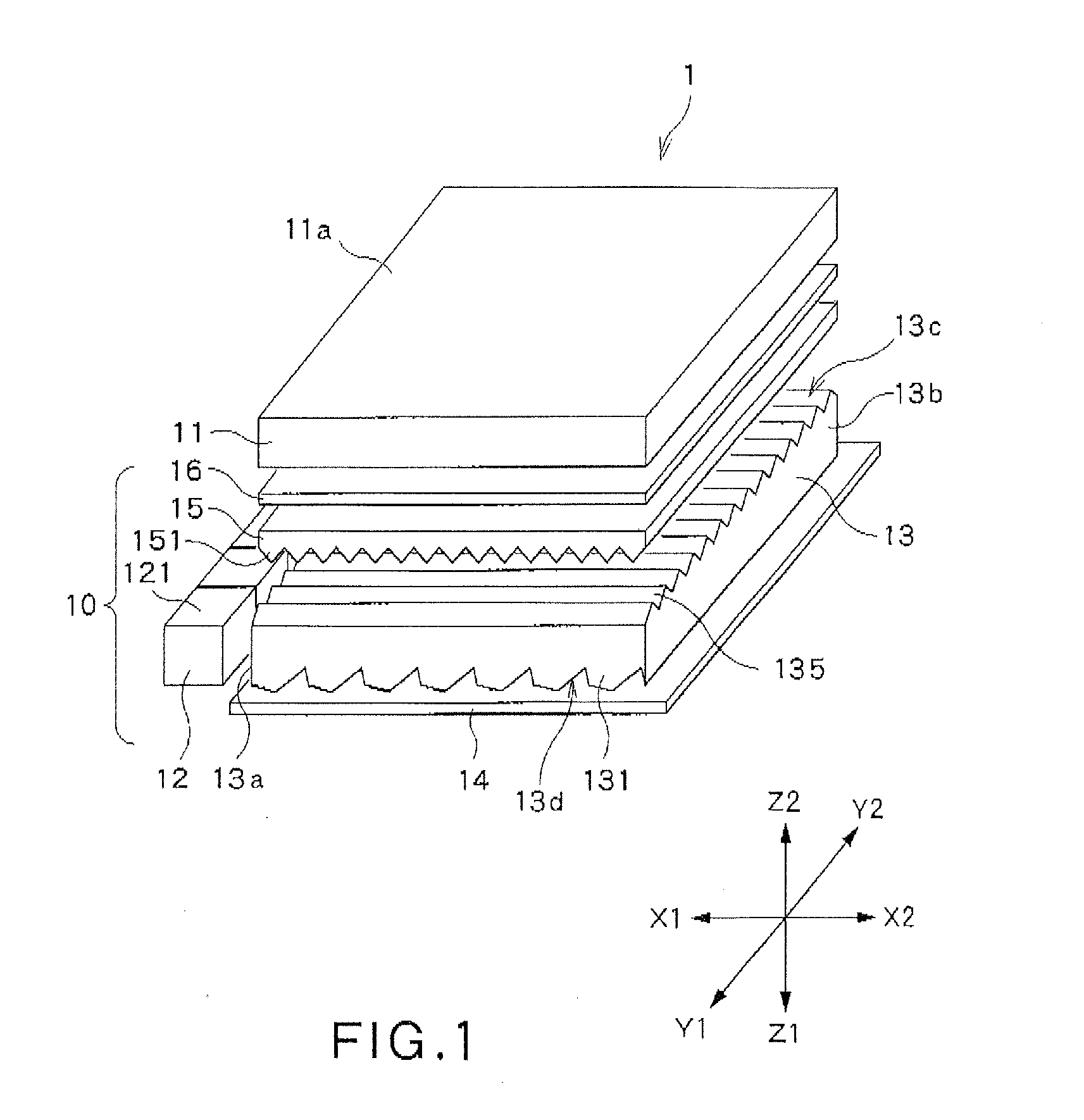
[0046]FIG. 1 is a diagram illustrating a transmission-type display device 1 according to an embodiment of the present invention.

[0047]The transmission-type display device 1 of this embodiment includes an LCD pane 11 and a surface source device 10. The transmission-type display device 1 illuminates the LCD panel 11 from the back by means of the surface source device 10 to display image information formed on the LCD panel 11.

[0048]In the following figures, including FIG. 1, and in the following description, the following X-, Y- and Z directions will be referred to for easier understanding: X direction (X1-X2 direction) and Y direction (Y1-Y2 direction) are perpendicular to each other and are both parallel to the screen of the transmission-type display device 1 in use; and Z direction (Z1-Z2 direction) is perpendicular to the screen of the transmission-type display device 1. The Z1 direction is a direction toward a viewer, while the Z2 direction is the opposite direction.

[0049]The surf...

experimental example

[0150]An experiment which was conducted on the above-described embodiment will now be described. The particulars of the light guide plate 13, the surface source device 10 and the transmission-type display device 1, which were used in the experiment, are as follows:

[0151]LCD panel 11: effective display screen size 294×165 mm

[0152]Light guide plate 13: made of acrylic resin, total thickness about 550 μm

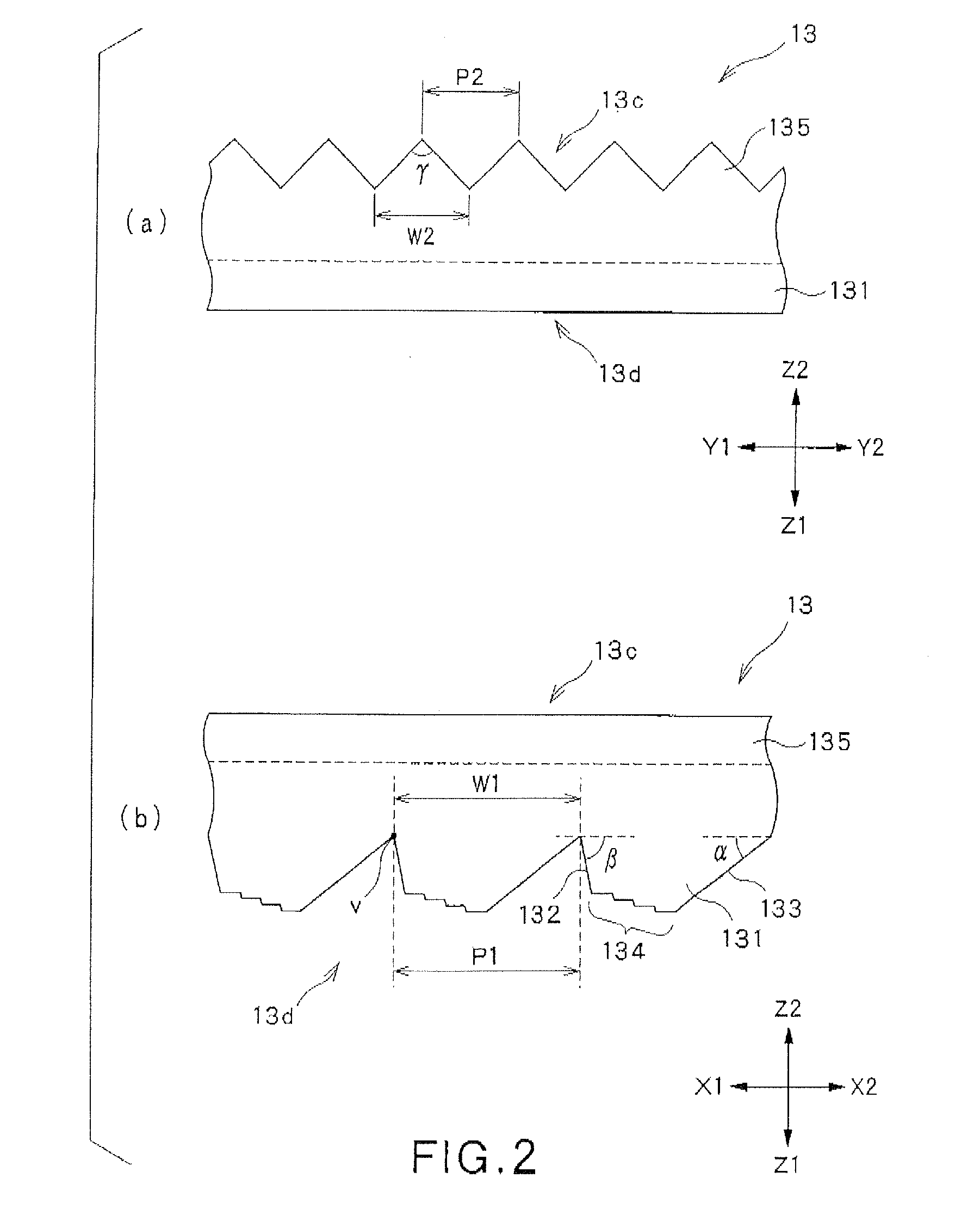
[0153]Back surface-side unit optical structures 131: pitch P1=100 μm, angle α=2°, angle β=70°, ratio Wb / W1 at the light entrance surface-side end=20 / 100, ratio Wb / W1 at the opposing surface-side end=80 / 100, difference in the Z1-direction height between the surfaces of the top surface region=about 0.1 μm

[0154]Light exit-side unit optical structures 135: pitch P2=50 μm, angle γ=12°

[0155]Reflective sheet 14: white PET (polyethylene terephthalate) resin sheet-like member

[0156]Prism sheet 15: prism substrate layer 152 comprised of a PET resin sheet-like member, thickness 125 μm; unit prisms ...


PUM


Abstract

A light guide plate 13 has a number of back surface-side unit optical structures 131 arranged in a back surface 13d along a light guide direction. Each back surface-side unit optical structure 131 is tapered in a direction away from a light exit surface 13c, and has a first inclined surface 132 lying on the light entrance surface side, a second inclined surface (133) lying opposite the first inclined surface and which totally reflects at least part of incident light, and a top surface region 134 lying between the first inclined surface 132 and the second inclined surface 133, and located farthest from the light exit surface 13c. The top surface regions 134 each include a plurality of surfaces 134a to 134d which are parallel to the light exit surface 13c and have different heights “h” in the direction away from the light exit surface 13c.

Description

TECHNICAL FIELD[0001]The present invention relates to a light guide plate, a surface source device and a transmission-type display device.BACKGROUND ART[0002]A transmission-type display device is known which illuminates a transmissive display, such as an LCD (Liquid Crystal Display) panel, from the back by means of a surface source device (backlight) to display images.[0003]Surface source devices are roughly classified into direct-light type devices which have a light source disposed right behind an optical member such as an optical sheet, and edge-light type devices which have a light source disposed lateral to an optical member. With a light source disposed lateral to an optical member such as a light guide plate, edge-light type surface source devices have the advantage that they can be designed to be thin as compared to direct-light type surface source devices, and have been widely used in recent years.[0004]In an edge-light type surface source device, a light source is generall...

Claims


Application Information

Patent Timeline
29 Jan 2015
Publication
US20150029745A1
IPC
F21V8/00
CPC
G02B6/0038; G02B6/005; G02B6/0058; G02B6/0053; G02B6/0055; G02B6/0016; G02B6/002
Inventors
ASANO, EIJI; YAMAMOTO, HIROSHI