
New energy vehicle and battery locking device thereof

a new energy vehicle and locking device technology, applied in the field of new energy vehicles and new energy vehicles, can solve the problems of limited capacity of electric vehicles, long time-consuming battery charging, and limited mileage of electric vehicles, and achieve the effect of convenient battery replacement, reduced time required for battery replacement, and simplified battery disassembly and assembly process

Active Publication Date: 2015-01-29
STATE GRID ZHEJIANG ELECTRIC POWER CO LTD HANGZHOU POWER SUPPLY CO +2
View PDF0 Cites 18 Cited by
  • Summary
  • Abstract
  • Description
  • Claims
  • Application Information

AI Technical Summary

Benefits of technology

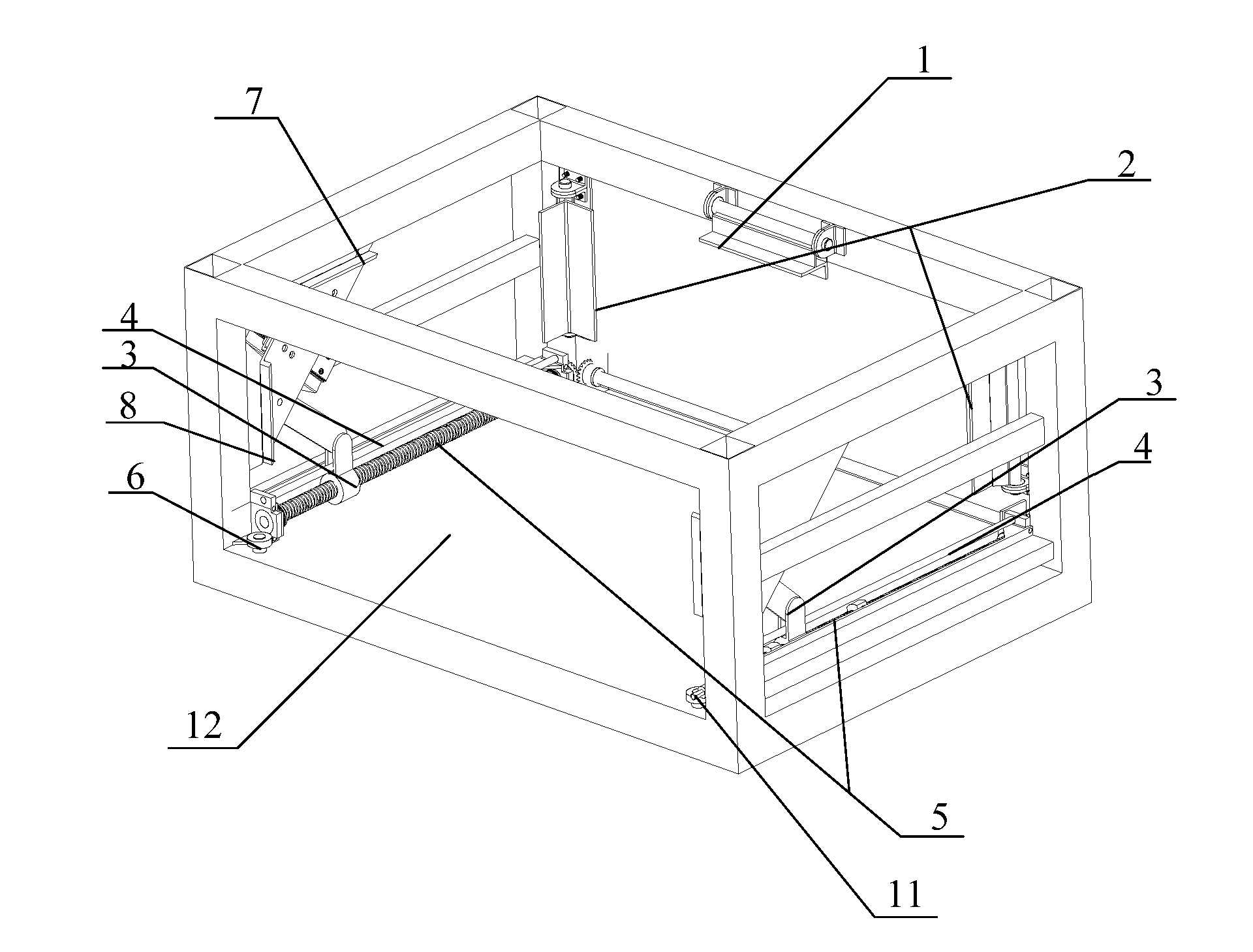
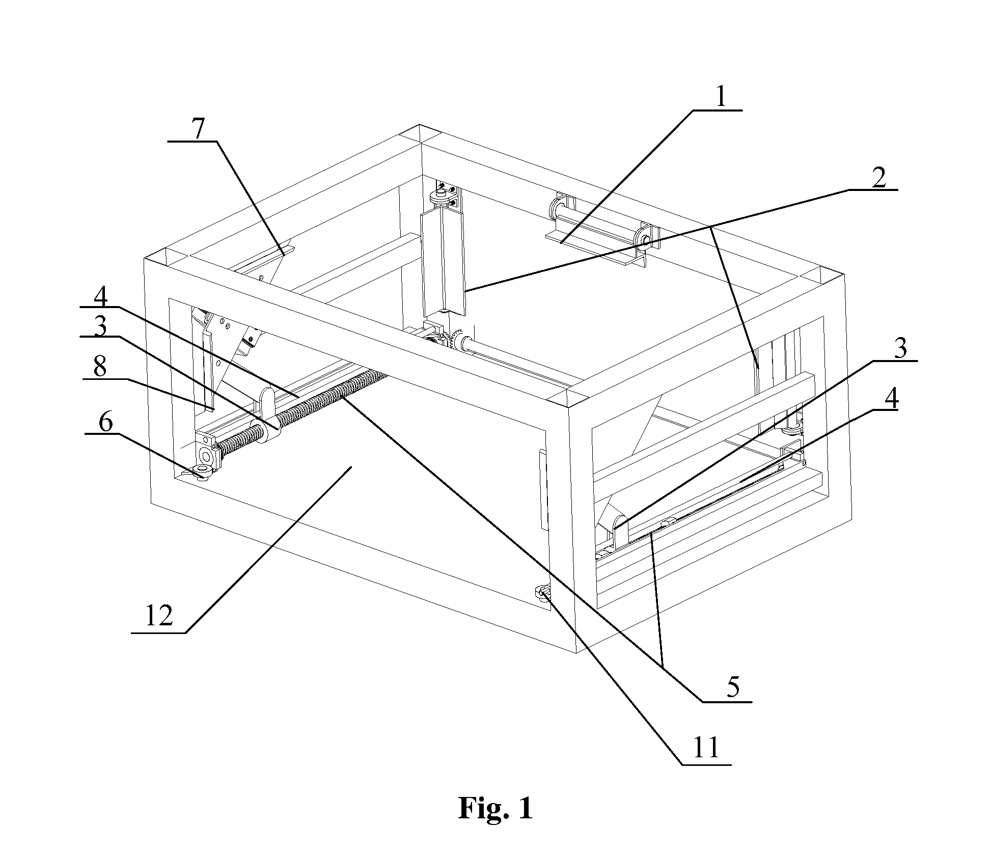
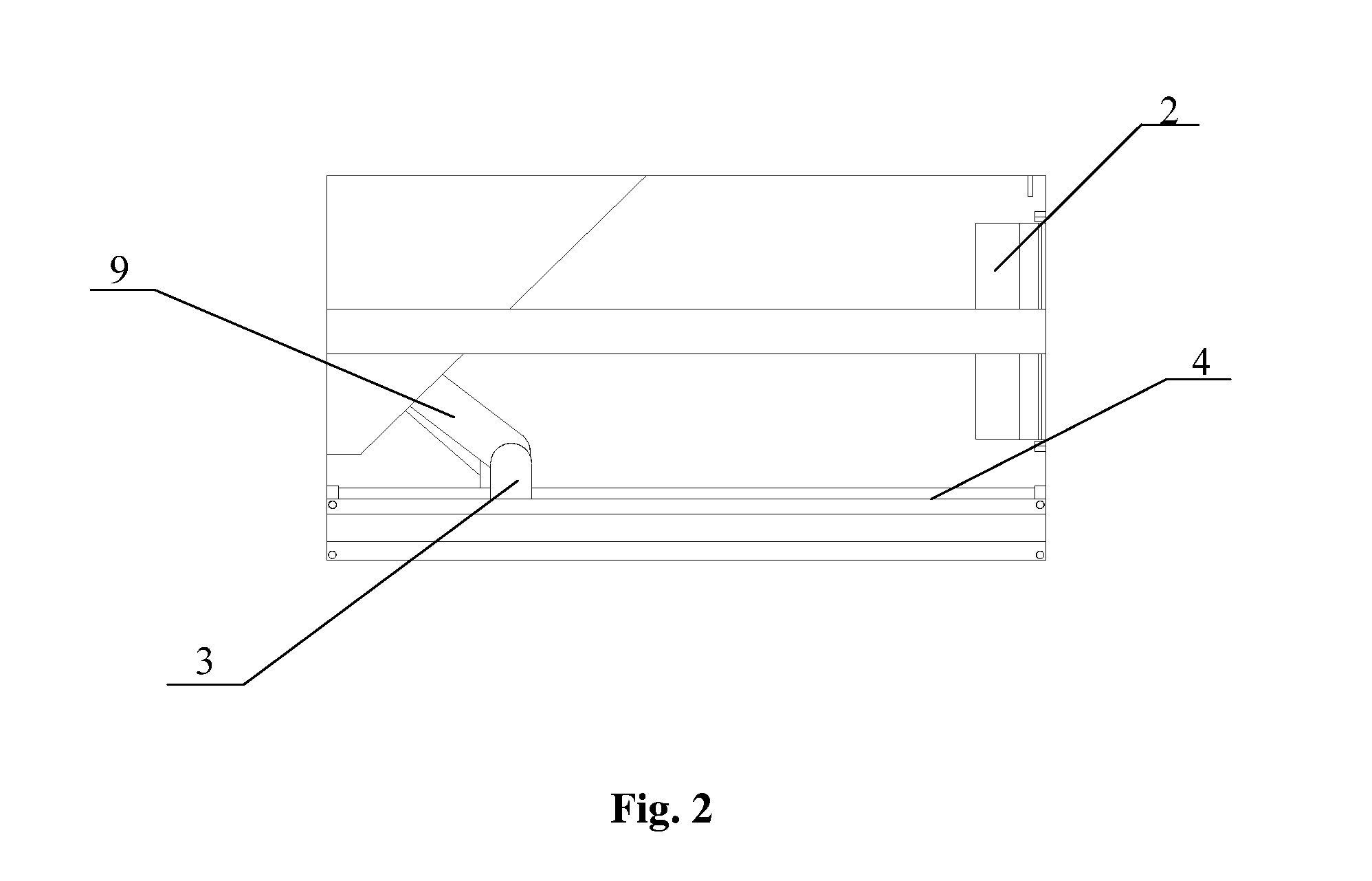
The present application is about a battery locking device for a new energy vehicle that allows for quick disassembly or assembly of the battery. Compared to traditional methods that use bolts to fix the battery, this device uses a linkage mechanism to secure or release the battery. This simplifies the process of replacing the battery and reduces the time required for replacement. The invention also provides a new energy vehicle with the battery locking device, making it convenient to change the battery.

Problems solved by technology

The battery of the electric vehicle has a limited capacity, and thus the electric vehicle can only run for a limited mileage.
However, it usually takes a long time to charge the battery, which is inconvenient for automobile users, especially for those who drive a bus mainly for passenger transportation.
As a result, not only the driver's time but also the passengers' trips are delayed.
It is easier for an operator to assemble / disassemble bolts near the operator, while it is difficult for an operator to assemble / disassemble bolts away from the operator, and it is extremely inconvenient to assemble / disassemble bolts between the battery and the battery compartment, which kind of replacing manner is complicated and a long time is spent for the replacing operation.
Therefore, a technical problem needed to be solved by the person skilled in the art is how to disassemble / assemble the battery of the new energy vehicle quickly and save the time for replacing the battery.

Method used


Image

  • New energy vehicle and battery locking device thereof
  • New energy vehicle and battery locking device thereof
  • New energy vehicle and battery locking device thereof

Examples


Embodiment Construction

[0030]An object of the present application is to provide a battery locking device for a new energy vehicle. In the battery locking device, a battery clamping device on the battery locking device is controlled by a linkage mechanism. Therefore the battery can be integrally clamped or released through a single operation, which effectively reduces the time required for replacing the battery. Another object of the present application is to provide a new energy vehicle with the battery clamping device.

[0031]In order that those skilled in the art can better understand solutions of the present application, the present application will be illustrated in detail in conjunction with the accompanying drawings and embodiments.

[0032]In the present application, the new energy vehicle mainly refers to the electric vehicle or a hybrid electrical vehicle having a battery. The present application is also applicable to a fuel vehicle with a battery. The battery locking device according to embodiments o...


PUM

PropertyMeasurementUnit
inner angleaaaaaaaaaa
Electric energyaaaaaaaaaa
timeaaaaaaaaaa

Abstract

A battery locking device for a new energy vehicle including: a battery compartment fit for a battery, the battery compartment being provided with a battery inlet; and a battery clamping device provided on the battery compartment and controlled by a linkage mechanism. Since the battery clamping device is controlled by the linkage mechanism, during the mounting or removing of the battery, the battery can be integrally clamped or released by merely operating an operating end of the linkage mechanism. Compared with the prior art in which the battery is fixed through bolts, the battery can be integrally clamped or released by the battery locking device through a single operation, which greatly simplifies the disassembling or assembling process of the battery and reduces the time required for replacing the battery. A new energy vehicle provided with the above battery locking device has the same advantages.

Description

[0001]This application claims the benefit of priority to Chinese Patent Application No. 201210097944.6, filed with the Chinese State Intellectual Property Office on Apr. 5, 2012 and entitled “NEW ENERGY VEHICLE AND BATTERY LOCKING DEVICE THEREOF”, the entire disclosure of which is incorporated herein by reference.FIELD OF THE INVENTION[0002]The present application relates to the manufacturing technology field for the new energy vehicle, and particularly to a new energy vehicle and a battery locking device thereof.BACKGROUND OF THE INVENTION[0003]The crisis of fossil energy speeds up the step of the substitution of traditional energy by new energy, and the Electric energy, which is one of the clean energy, is widely used in various fields.[0004]Presently, the electric automobile is available, which mainly uses a storage battery as the electric power carrier, such that the motor of the electric automobile is rotated under the discharging of the storage battery, the motor in turn drive...

Claims


Application Information

Patent Timeline
Patent Type & Authority Applications(United States)
IPC IPC(8): H01M2/10H01M50/264
CPCH01M2220/20H01M2/1083Y02E60/10H01M50/264
Inventor ZHANG, FANZHENG, ZHENGXIANLIN, XIAOBINDENG, GUANGBINDAI, YONGXIA
Owner STATE GRID ZHEJIANG ELECTRIC POWER CO LTD HANGZHOU POWER SUPPLY CO
Learn More