
Range shifter and particle radiotherapy device

a radiotherapy device and range shifter technology, applied in radiation therapy, x-ray/gamma-ray/particle irradiation therapy, radiation therapy, etc., can solve problems such as time-consuming, and achieve the effect of accurate irradiation field

Inactive Publication Date: 2015-01-29
MITSUBISHI ELECTRIC CORP
View PDF2 Cites 15 Cited by
  • Summary
  • Abstract
  • Description
  • Claims
  • Application Information

AI Technical Summary

Benefits of technology

The invention is a range shifter that can adjust the energy of a particle beam accurately. It can do this even when the incident particle beam condition changes. This ensures that the particle beam therapy system can create an accurate irradiation field.

Problems solved by technology

Although the energy of the particle beam is adjustable by changing the condition of the accelerator, it takes time.

Method used


Image

  • Range shifter and particle radiotherapy device
  • Range shifter and particle radiotherapy device
  • Range shifter and particle radiotherapy device

Examples


embodiment 1

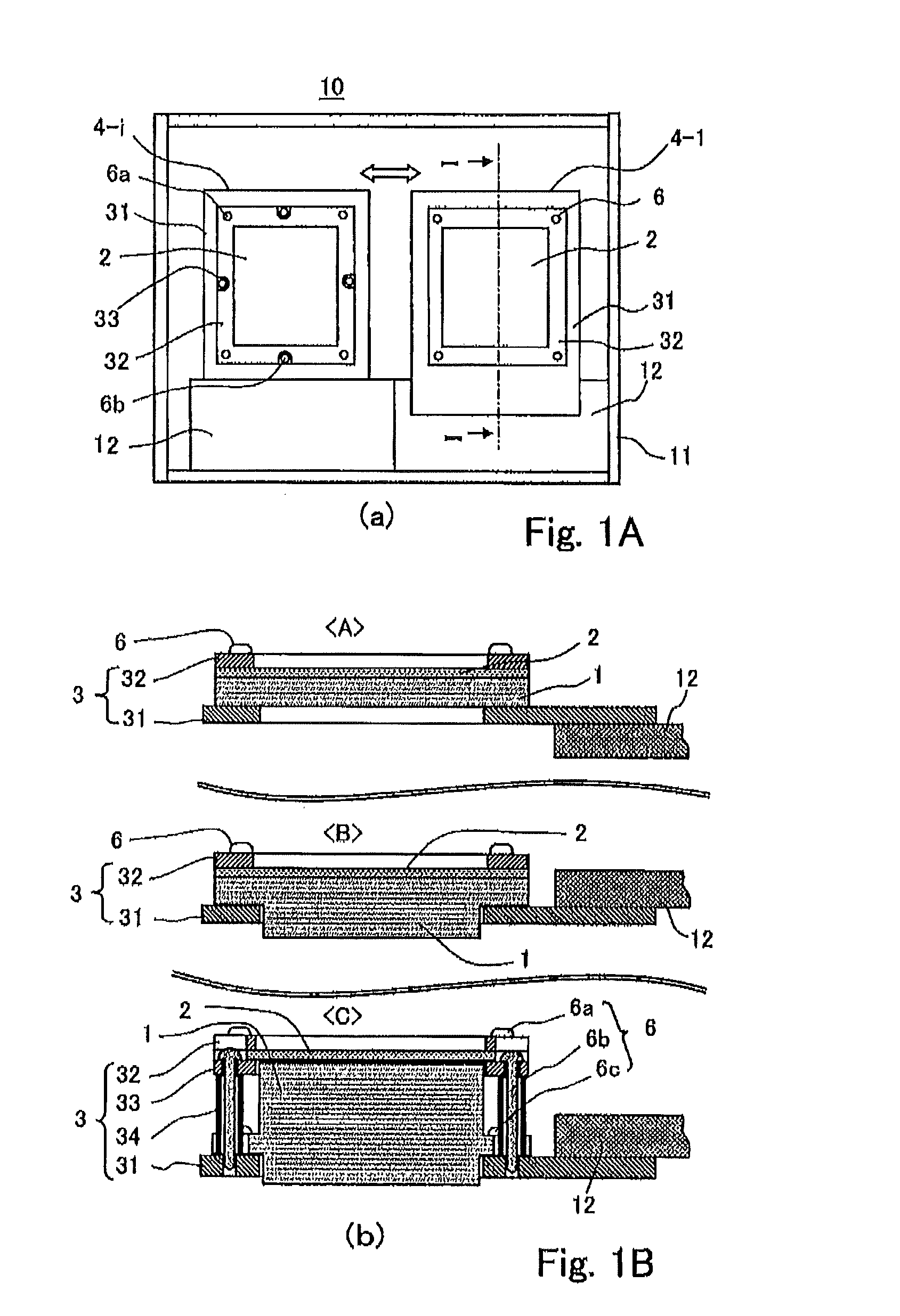
[0021]Hereinafter, a configuration of a range shifter according to Embodiment 1 of the invention and a method of adjusting the same, will be described. FIG. 1 to FIG. 4 are for illustrating the range shifter and its adjusting method according to Embodiment 1 of the invention, in which shown at FIG. 1(a) and FIG. 1(b) are a top view (a) showing the configuration of the range shifter, and cross-sectional views (b) taken along line I-I in the top view, individually showing transmissive units of typical three types that are different depending on a thickness of the transmissive plate.

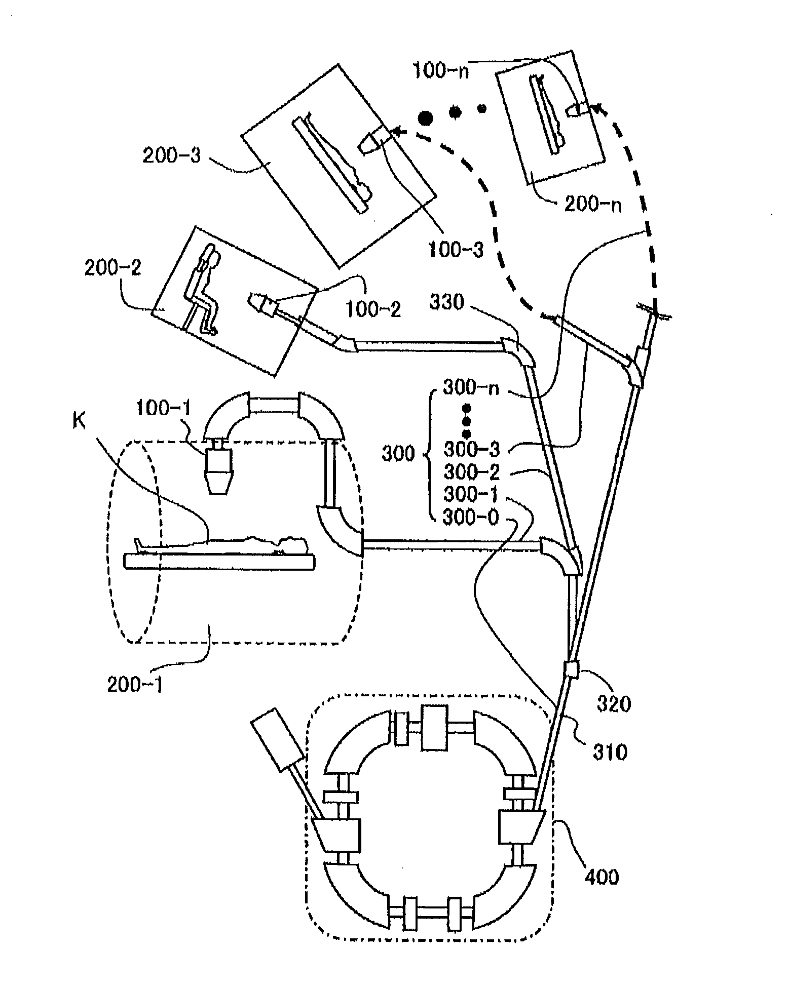
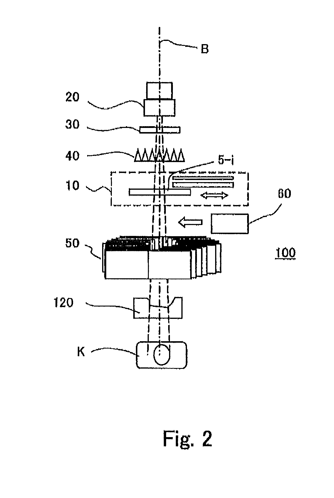
[0022]Meanwhile, FIG. 2 is a schematic diagram showing a configuration of an irradiation device provided with the range shifter according to Embodiment 1 of the invention. FIG. 3 is a diagram showing a configuration of a particle beam therapy system provided with the aforementioned irradiation device in each treatment room. Further, FIG. 4 is a flowchart for illustrating a method of adjusting the range shif...


PUM


Abstract

There is provided a range shifter which includes a transmissive plate whose thickness has been adjusted depending on a setup value of an amount of energy to be attenuated, and a holder portion that holds the transmissive plate, wherein the thickness of the transmissive plate is adjusted to be a thickness equivalent to an attenuation amount lower than the setup value by a predetermined rate thereof; and wherein, a superimposing mechanism capable of releasably superimposing an adjustment sheet over the transmissive plate, is provided to at least one of the transmissive plate and the holder portion, the adjustment sheet being adjusted to have a thickness equal to or less than a thickness equivalent to a two-fold attenuation amount of the predetermined rate.

Description

TECHNICAL FIELD[0001]The present invention relates to a particle beam therapy system for performing a treatment through irradiation with a particle beam, and in particular, to a range shifter for adjusting a range of the particle beam.BACKGROUND ART[0002]A particle beam therapy, which is a treatment of a deceased tissue by irradiating it with a particle beam to thereby damage the tissue, is a part of broad-sense radiation therapy. However, unlike a y-ray, an X-ray or like other ray, the imparted dose of a particle beam such as a proton beam, a heavy ion beam, etc., becomes maximum abruptly in a specific depth range (Bragg peak) in a body according to energy of the particle beam. Thus, in the particle beam therapy, it is possible to control the irradiation region (irradiation field), not only as a planar shape, but also in a depth direction by adjusting the energy.[0003]Meanwhile, since the facility of an accelerator that is a beam source for the particle beam therapy is huge, the pa...

Claims


Application Information

Patent Timeline
IPC IPC(8): A61N5/10
CPCA61N5/1079A61N5/1048A61N5/1043A61N2005/1087A61N2005/1095G21K1/10
Inventor YAMAMOTO, HIROHIDEHAGINO, TAKESHIINOUE, HIROMITSU
Owner MITSUBISHI ELECTRIC CORP
Learn More