Wiring harness

a wiring harness and wire harness technology, applied in the direction of insulated conductors, cables, electric/fluid circuits, etc., can solve the problems of high painting cost, achieve the effect of reducing material costs, facilitating the bending work of conduit members, and implementing more inexpensively

Active Publication Date: 2015-02-05
YAZAKI CORP
View PDF13 Cites 2 Cited by
  • Summary
  • Abstract
  • Description
  • Claims
  • Application Information

AI Technical Summary

Benefits of technology

[0015]The partial application of the resin identifying portion is effective, for example, when a fixing clamp is provided. This is because even though the resin identifying portion is applied to a location where a fixing clamp is to be attached, the resin identifying portion is hidden or covered by the fixing clamp attached. Thus, there is no reason for the application of the resin identifying portion to such a location. In addition, it is also effective to provide the resin identifying portion only on the straight portions of the conduit member, excluding the bent portions. This is because this facilitates the bending work of the conduit member. Providing the resin identifying portion near the bent portion is good enough to issue a warning about the high-voltage current. The partial application of the resin identifying portion is also effective to reduce the material costs.
[0016]According to the invention, since the resin identifying portion is formed by extruding the resin or by winding the resin sheet

Problems solved by technology

Incidentally, since the wiring harness including the metallic conduit member colored orange is also laid outside a passenger compartment (on an underside of a bod

Method used


Image

  • Wiring harness
  • Wiring harness
  • Wiring harness

Examples


embodiment 1

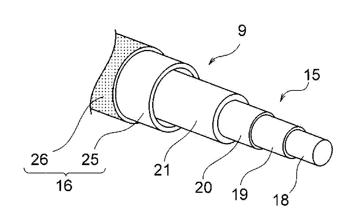
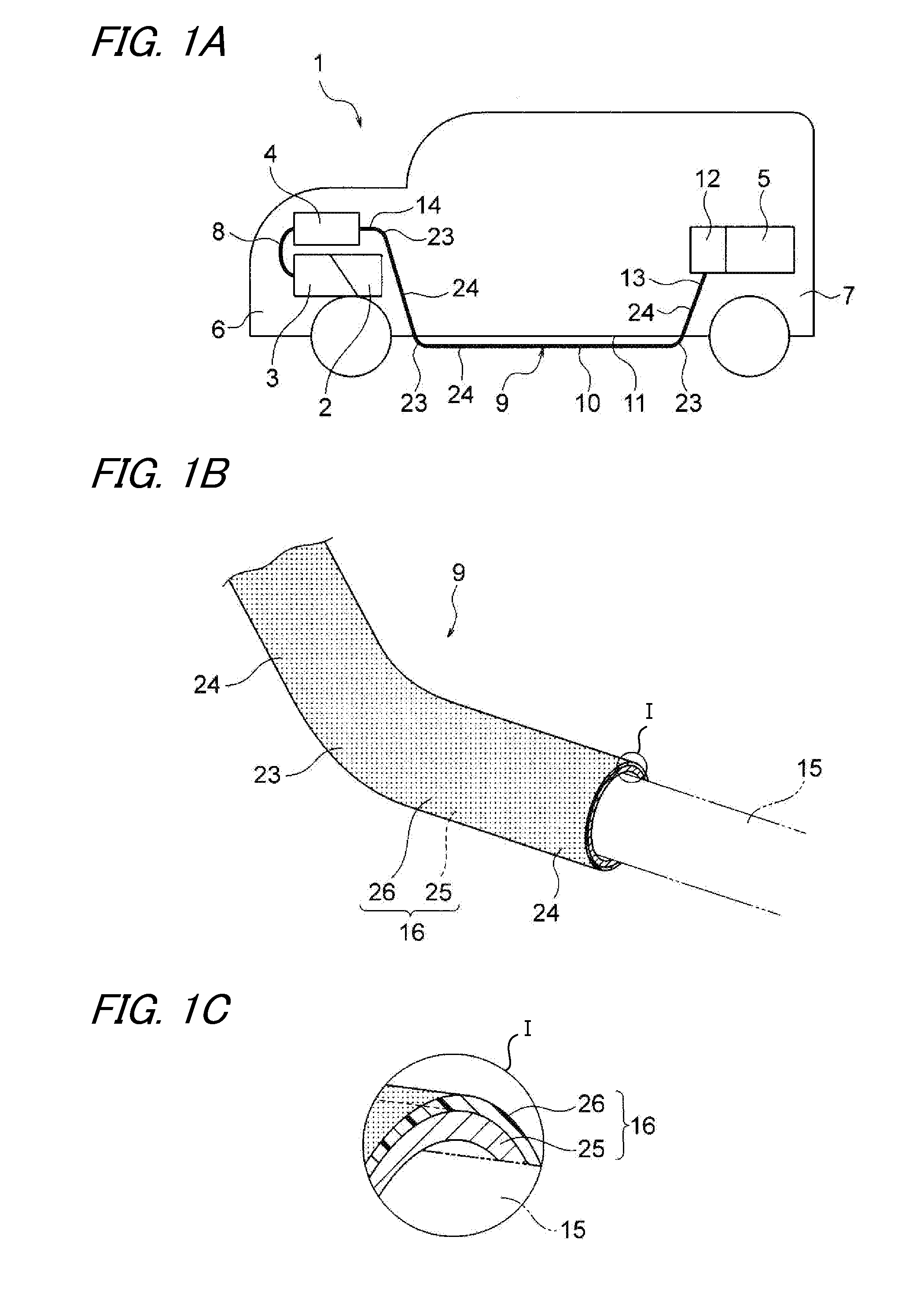
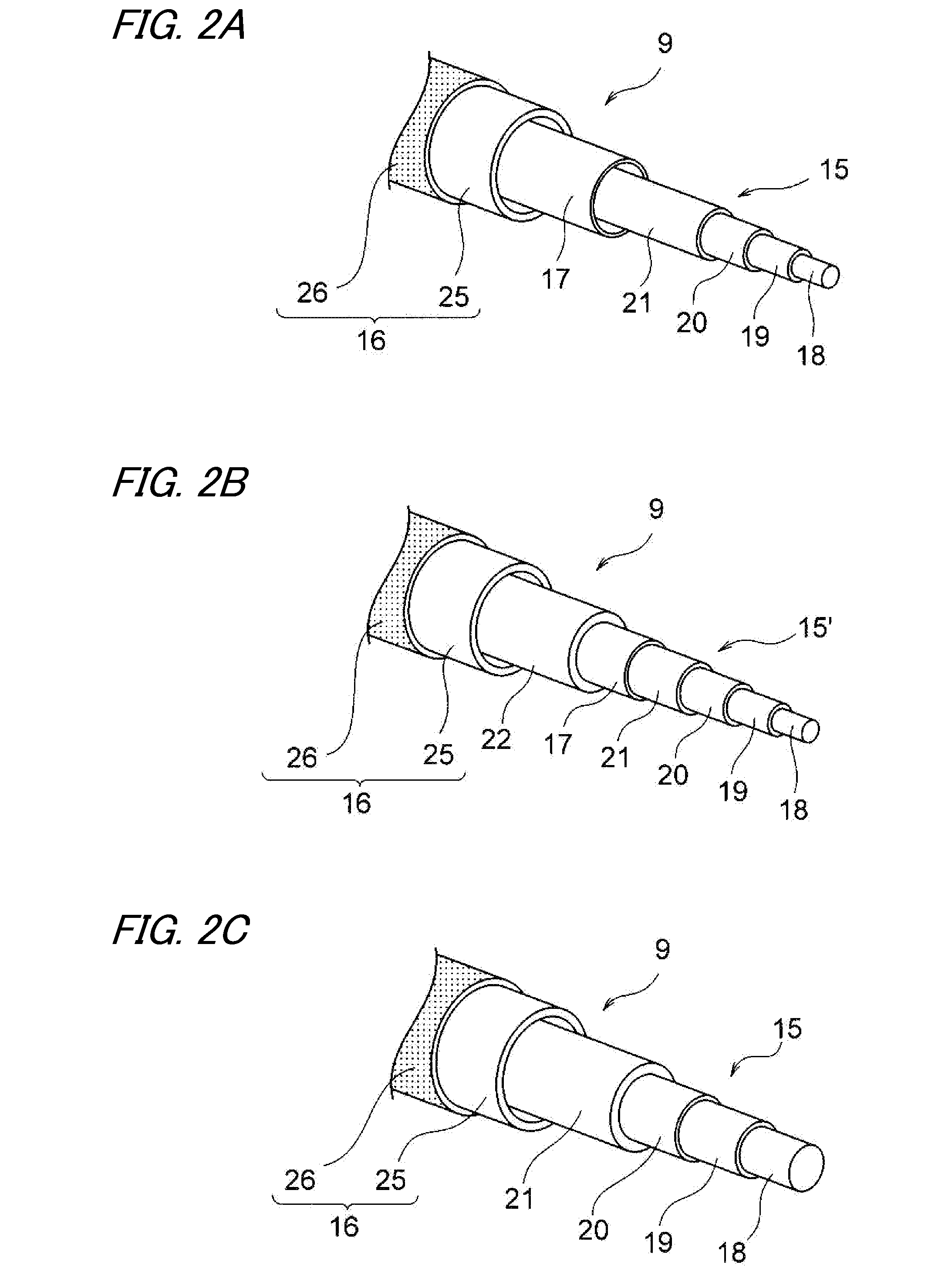
[0024]Hereinafter, Embodiment 1 will be described by reference to the drawings. FIGS. 1A to 1C show a wiring harness of the invention, of which FIG. 1A shows a layout of the wiring harness, FIG. 1B shows the configuration of the wiring harness, and FIG. 1C is an enlarged view of an encircled portion I in FIG. 1B. Further, FIGS. 2A to 2C show configurations of conductor lines of the wiring harness.

[0025]In this embodiment, the invention will be described as being applied to a wiring harness which is laid out on a hybrid vehicle (or to a wiring harness which is laid out on an electric vehicle or a general vehicle with an internal combustion engine).

[0026]In FIG. 1A, reference numeral 1 denotes a hybrid vehicle. A hybrid vehicle 1 is a vehicle which is driven by power from a combination of such power sources as an engine 2 and a motor unit 3. Electric power from a battery 5 (a battery pack) is supplied to the motor unit 3 via an inverter unit 4. In this embodiment, the engine 2, the mo...

embodiment 2

[0041]Hereinafter, referring to the drawings, Embodiment 2 will be described. FIG. 3 is a perspective view of a resin identifying portion 26 and a non-identifying portion 27 which are provided on an outer surface of a conduit member. In addition, FIG. 4 is a perspective view showing a state in which a clamp is retrofitted to the non-identifying portion. It should be noted that like reference numerals will be given to basically like constituent members to those of Embodiment 1, and a detailed description thereof will be omitted here.

[0042]In FIG. 3, a sheathing member 16 includes a conduit member 25, resin identifying portions 26 which are provided so as to cover an outer surface of the conduit member 25 and non-identifying portions 27 which are portions where resin identifying portions 26 are not provided circumferentially on the conduit member 25. The sheathing member 16 of Embodiment 2 includes the resin identifying portions 26 which are provided partially on the conduit member 25...


PUM


Abstract

A wiring harness includes one or a plurality of conductor lines and a conduit member which accommodates therein the conductor line or lines, an identification in a predetermined color being applied to an outer surface of the conduit member. A resin identifying portion is formed on the outer surface of the conduit member by extruding a resin, or a resin sheet material or tape material is wound around the outer surface of the conduit member that is formed as the resin identifying portion.

Description

CROSS REFERENCE TO RELATED APPLICATIONS[0001]This application is a continuation of PCT application No. PCT / JP2013 / 061703, which was filed on Apr. 16, 2013 based on Japanese Patent Application (No. 2012-093520) filed on Apr. 17, 2012, the contents of which are incorporated herein by reference.BACKGROUND OF THE INVENTION[0002]1. Field of the Invention[0003]The present invention relates to a wiring harness including a conduit member which accommodates therein a conductor line.[0004]2. Description of the Related Art[0005]A wiring harness is provided in a mobile means such as a motor vehicle to electrically connect equipment mounted. A wiring harness described in JP-A-2004-224156 below includes three high tension electric wires and three metallic conduit members (metallic pipes) which accommodate individually the three high tension electric wires for protection. The high tension electric wires are provided to connect a motor mounted in a front portion of a vehicle and an inverter mounted...

Claims


Application Information

Patent Timeline
IPC IPC(8): B60R16/02H02G3/04
CPCH02G3/0406B60R16/0215H02G3/0481H02G3/32
Inventor YOSHIDA, HIROYUKIADACHI, HIDEOMI
Owner YAZAKI CORP
Why Eureka
Try Eureka