Solar Panel Mounting Structure

a solar panel and mounting structure technology, applied in the direction of heat collector mounting/support, photovoltaic support, light and heating apparatus, etc., can solve the problems of large amount of potential energy lost by stationary pv panel, time-consuming and laborious to accurately assemble and align the mounting structure, solar panel assembly,

a solar panel and mounting structure technology, applied in the direction of heat collector mounting/support, photovoltaic support, light and heating apparatus, etc., can solve the problems of large amount of potential energy lost by stationary pv panel, time-consuming and laborious to accurately assemble and align the mounting structure, solar panel assembly,

US20150034575A1Inactive Publication Date: 2015-02-05MAGNA INTERNATIONAL INC

Image

  • Solar Panel Mounting Structure
  • Solar Panel Mounting Structure
  • Solar Panel Mounting Structure

Examples


Embodiment Construction

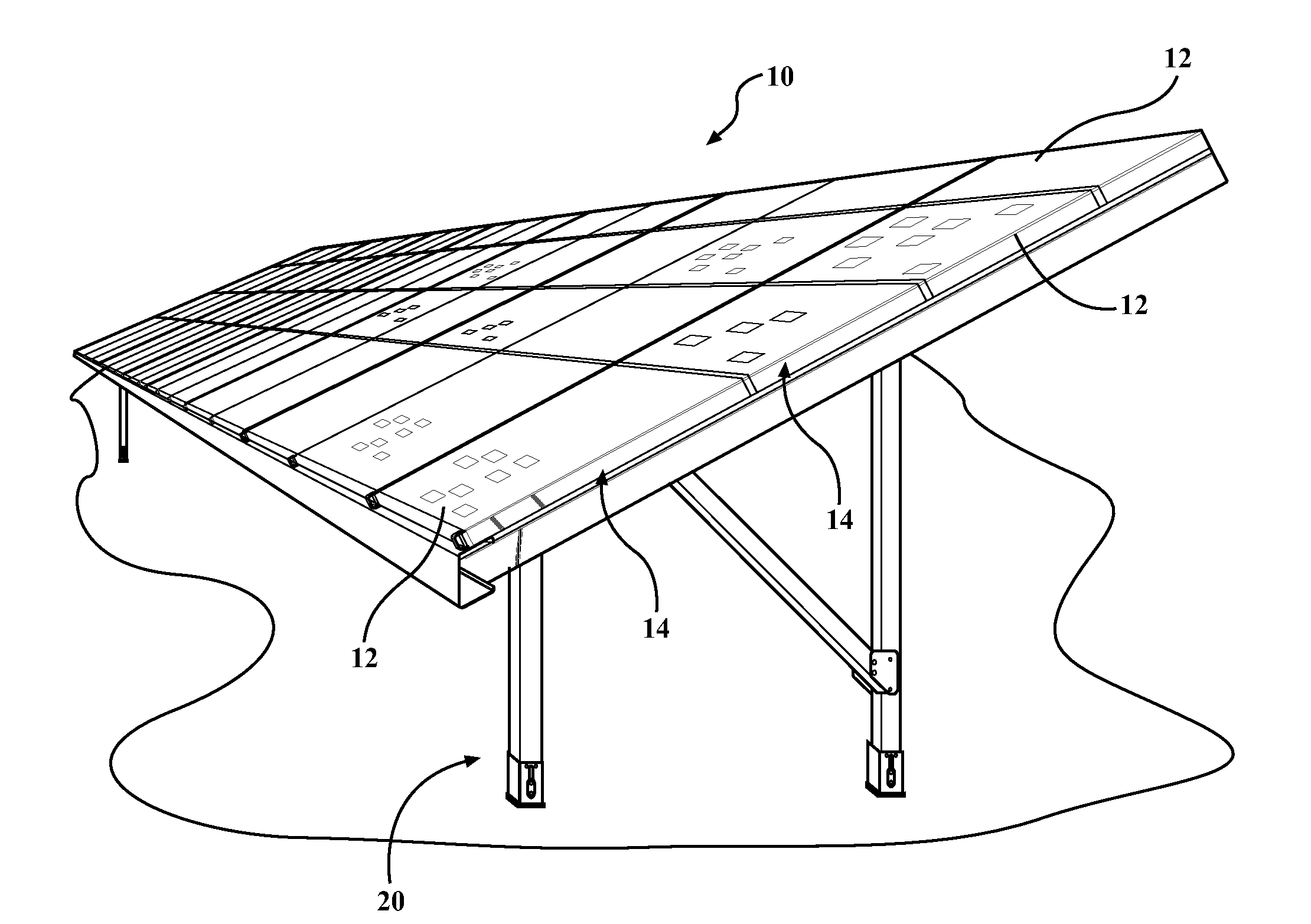
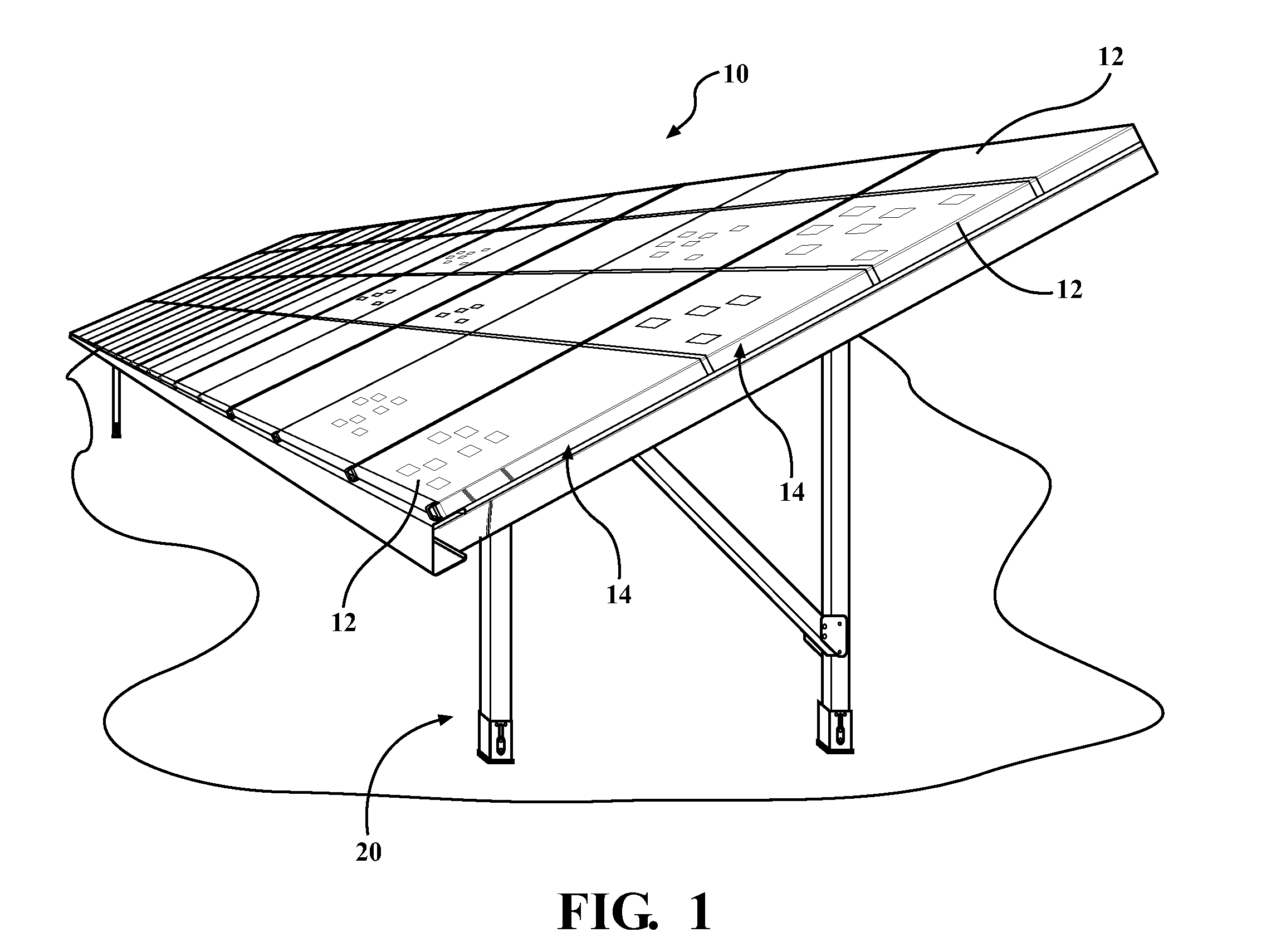
[0027]Referring to the Figures, wherein like numerals indicate corresponding parts throughout the several views, a solar assembly 10 is generally shown. As best shown in FIG. 1, the solar assembly 10 may include a plurality of panels 12 arranged in a plurality of solar arrays 14. In the exemplary embodiment, each panel 12 can include at least one photovoltaic (PV) cell for receiving sun rays and converting them into electricity. However, it should be appreciated that the solar panels 12 could be any other type of panel for converting sun rays into electricity or any other form of useable energy. It should be appreciated that the solar assembly 10 could include any number of solar arrays 14 and those arrays 14 could be disposed at any desirable angle relative to one another. According to an aspect, the solar arrays 14 are supported and oriented in a predetermined direction and at a predetermined angle by a mounting structure 20. According to an aspect, the solar arrays 14 are install...


PUM


Abstract

A mounting structure for a solar panel assembly, having a plurality of solar panels, includes a plurality of vertical support legs and a grid assembly. The grid assembly includes a plurality of north-south members and the east-west members. The plurality of north-south members include a plurality of elongated slots to allow attachment to the vertical support legs despite any manufacturing tolerances that may exist in the components. The plurality of east-west members include a plurality of elongated slots to allow attachment to the north-south members despite any manufacturing tolerances that may exist in the components.

Description

CROSS REFERENCE TO RELATED APPLICATIONS[0001]This PCT Patent Application claims the benefit of U.S. Provisional Patent Application Ser. No. 61 / 611,217, entitled “Solar Panel Mounting Structure”, filed Mar. 15, 2012, the entire disclosure of the application being considered part of the disclosure of this application, and hereby incorporated by reference.BACKGROUND OF THE INVENTION[0002]1. Field of the Invention[0003]The subject invention is related to a solar panel assembly, and more precisely, to a solar panel assembly including a mounting structure for receiving and retaining solar panels.[0004]2. Description of the Prior Art[0005]Renewable resources are becoming an increasingly popular alternative to non-renewable resources for generating electricity. One renewable resource that can be converted into electricity is solar energy through the use of solar power generators, which harness the potential energy of solar rays from the sun and convert that potential energy into electricity...

Claims


Application Information

Patent Timeline
05 Feb 2015
Publication
US20150034575A1
IPC
H01L31/042; F24J2/52; H01L31/05
CPC
H01L31/0422; H01L31/05; F24J2/525; F24J2/5245; F24J2/523; Y02E10/50; H02S20/00; H02S20/10
Inventors
WARPUP, RYAN ROBERT; WERNER, MARK FRANCIS