
Three-dimensional image program and printer

Active Publication Date: 2015-02-05
SEIKO EPSON CORP
View PDF4 Cites 2 Cited by
  • Summary
  • Abstract
  • Description
  • Claims
  • Application Information

AI Technical Summary

Benefits of technology

The patent describes a method for making a virtual three-dimensional image that changes based on the angle at which it is viewed. The method includes applying deterioration processing to one of the images, making it more transparent as its position in the image changes. This allows for easier adjustment of specific parts of the image, as the result is reflected to other images in the set. Overall, the method reduces the amount of work required by the user to create and adjust the image.

Problems solved by technology

It is necessary to prevent a lens sheet from a printing error since the lens sheet is relatively expensive.
For example, a print resolution or a print position precision of an ink-jet printer is relatively low in comparison with a commercial printer that performs screen-printing or an offset printing, and in addition, the ink ejected on a recording medium is relatively and easily bled.
Also, as the resolution of print dots is low, an image tends to be blurred.
However, the reduction (deterioration) of resolution in a lens orthogonal direction of a cylindrical lens, the print resolution in a printer that is lower than a display resolution in a display section, the reduction (deterioration) of image quality when a three-dimensional image is viewed through the lens layer due to at least various problems such as the position precision of print dots, the bleeding of ink, etc. are not reflected.
Therefore, there is a problem that the user is disappointed because the image quality is low when it is viewed through the lenticular lens after the three-dimensional image was printed.
The aforementioned problems are not limited to the ink-jet printer, and the same problems are applied to printers that other printing methods are employed.
Also, it is not limited to the case that a three-dimensional image is printed on the lens sheet, and the same problems are also applied to the case that a lens layer such as a lenticular lens, etc. is bonded after the three-dimensional image was printed on a print medium, or a lens layer is formed on a print medium on which a three-dimensional image was printed by, for example, using an ink-jet recording method.
Further, it is not limited to a lenticular lens, and the same problems are also applied when other types of lens layers are used.
Thus, when the density of the pixels is high (dense) at the time of printing, the ink amount per unit area increases, and it easily bleeds to a division compression image of an adjacent image.
That is, the deterioration processing is applied to the pixels that the ink amount is large and the ink is easily bled when it is converted from the display color system to the print color system.
According to this structure, when the border part of the division compression image is protruded to the adjacent division compression image region, the image of the protruded part that should not be essentially seen is viewed through the lenses, and it causes the blurring of the image.

Method used


Image

  • Three-dimensional image program and printer
  • Three-dimensional image program and printer
  • Three-dimensional image program and printer

Examples


first embodiment

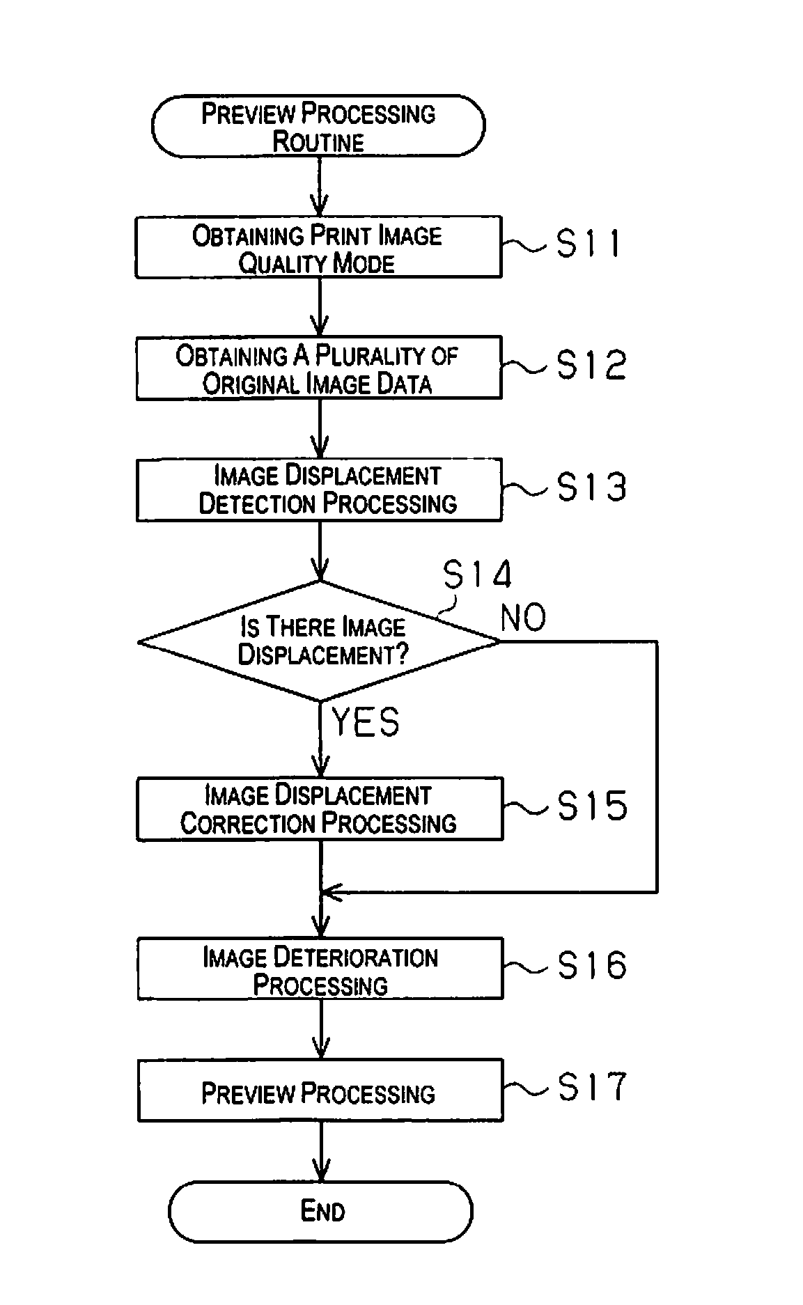
[0064]Hereinafter, one embodiment of programs and a printer will be explained in reference to FIG. 1 to FIG. 11.

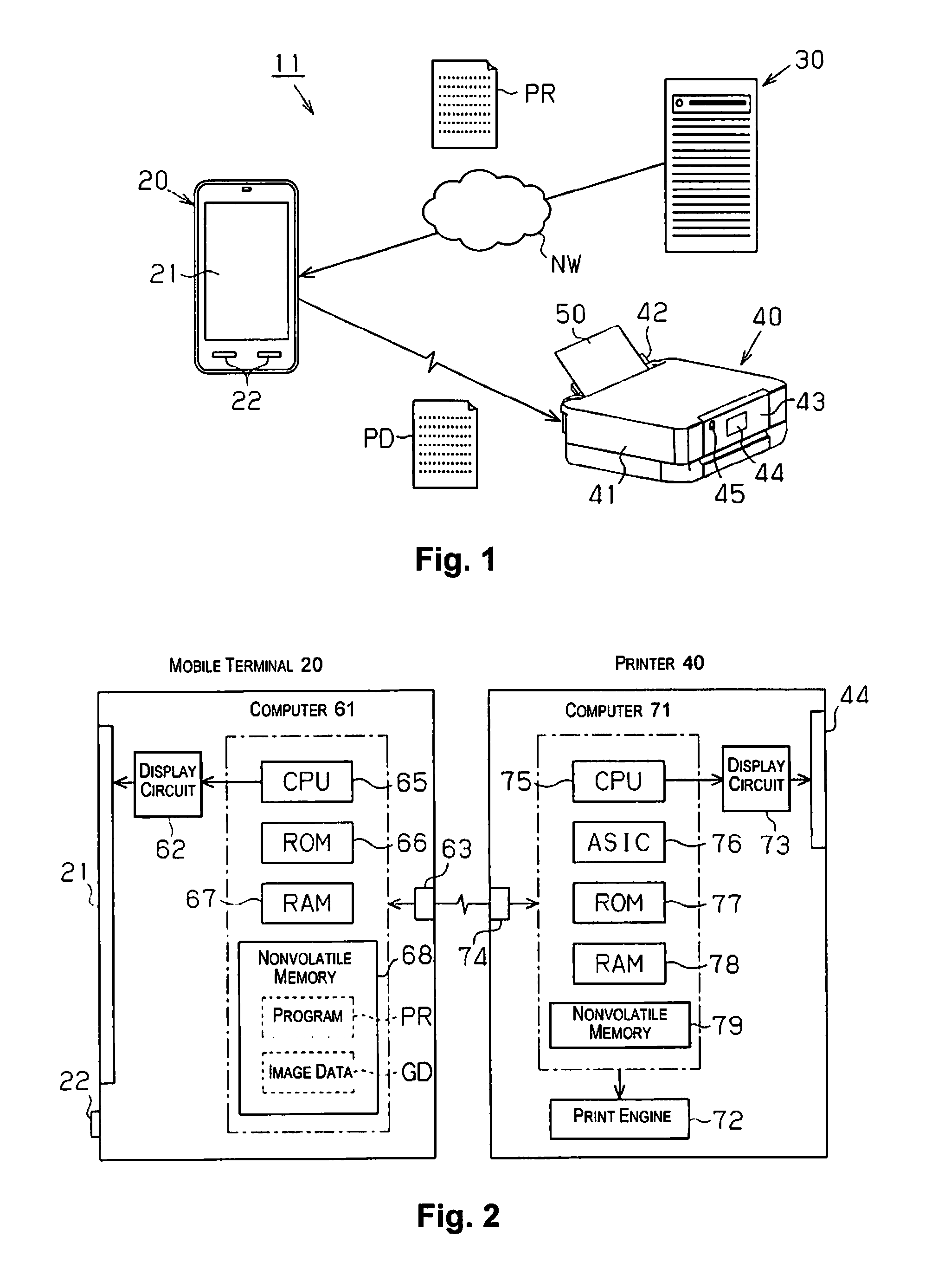
[0065]A print system 11 as shown in FIG. 1 is a system that can print a three-dimensional image on a lens sheet. The print system 11 is provided with a mobile terminal 20 that performs operations to instruct a displaying or a printing an image by the user, a server 30 that provides contents aimed at printing of the three-dimensional image to the mobile terminal 20, and a printer 40.

[0066]The plural kinds of contents are stored in the server 30. The user downloads the program PR to the mobile terminal 20 through the interne NW in a charge or free of charge. The program PR downloads a part of the contents with the desired tertiary viewing image data GD.

[0067]The mobile terminal 20 is provided with a display section 21 and an operating section and the screen of the display section 21 is capable of performing touch operations so as to operate various instructions. The display ...

second embodiment

[0135]The second embodiment will be described in reference to FIGS. 12A-C and FIG. 13.

[0136]A three-dimensional image of the present embodiment is a stereoscopic image that is capable of stereoscopically viewing through the lens layer by using disparity of left and right eyes, and has an image for left eye and an image for right eye as a plurality of images configuring the three-dimensional image. To provide the stereoscopic image, for example, the user takes two images having disparity by a camera, and determines whether or not these two images viewed from different angles are appropriate for using as the three-dimensional image.

[0137]As shown in FIG. 12A, the height positions of an object OP1 (object) in an image for left eye LG1 and an object OP2 in an image for right eye RG1 are calculated, and both height positions are compared and a displacement amount ΔL in the height direction (lens longitudinal direction LY) is detected. For example, the computers 61, 71 specify a position ...


PUM


Abstract

A virtual displaying method of a three-dimensional image for displaying at least one image of a plurality of images configuring a virtual three-dimensional image providing a three-dimensional visualization through a lens layer having a plurality of lenses includes applying a deterioration processing to the at least one image, and displaying, in a display section, an obtained image by the deterioration processing.

Description

CROSS-REFERENCE TO RELATED APPLICATIONS[0001]This application claims priority to Japanese Patent Application No. 2013-161696 filed on Aug. 2, 2013. The entire disclosure of Japanese Patent Application No. 2013-161696 is hereby incorporated herein by reference.BACKGROUND[0002]1. Technical Field[0003]The present invention relates to a three-dimensional image program and a printer to display a three-dimensional image, which is capable of displaying a three-dimensional visualization through a lens layer having a plurality of lenses, in a display section.[0004]2. Related Art[0005]A technology is disclosed, in which a three-dimensional image is printed on a lens sheet having a plurality of lenses (e.g., cylindrical lenses) such as lenticular lenses, etc., to enable three-dimensional visualization of an image (Japanese Laid-open Patent Application Publication No. 2001-42462 and Japanese Laid-open Patent Application Publication No. 7-281327, etc.). As a three-dimensional image, it includes ...

Claims


Application Information

Patent Timeline
IPC IPC(8): G06K15/02G02B30/27
CPCG06K15/1872G03B35/00H04N1/40093G02B30/34G03B35/18G03B25/02G03B35/24G02B30/27
Inventor NAKANO, TOMOYUKISUZUKI, KATSUHITOSHIROTORI, HIROSHI
Owner SEIKO EPSON CORP
Learn More