Lens for projection and projection-type display apparatus

a technology of projection and display apparatus, applied in the field of projection and can solve problems such as the risk of deterioration of lens performance, and achieve the effects of excellent optical performance, small size of projection type display apparatus, and high brightness

Inactive Publication Date: 2015-02-05
FUJIFILM CORP
View PDF2 Cites 13 Cited by
  • Summary
  • Abstract
  • Description
  • Claims
  • Application Information

AI Technical Summary

Benefits of technology

[0042]The lens for projection of the present invention substantially consists of three lens groups of the negative lens group, the positive lens group and the positive lens group arranged in this order from the magnification side. Further, the reduction side is telecentric, and the structure of the most magnification-side lens and the third lens group is appropriately set. Therefore, a small F-number, a wide angle of view and excellent optical performance are achievable at the sam

Problems solved by technology

Therefore, in a high-brightness projection-type display apparatus of recent years, there is a ris

Method used


Image

  • Lens for projection and projection-type display apparatus
  • Lens for projection and projection-type display apparatus
  • Lens for projection and projection-type display apparatus

Examples


example 1

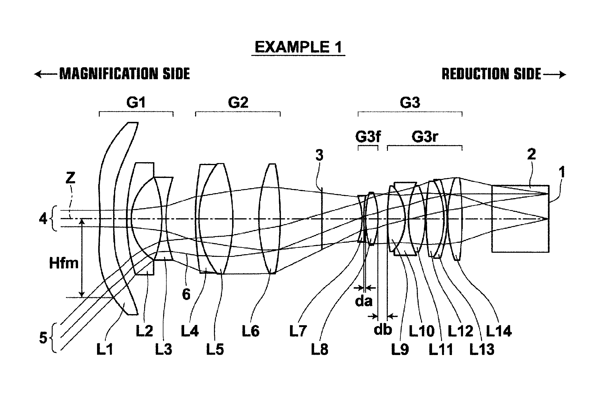
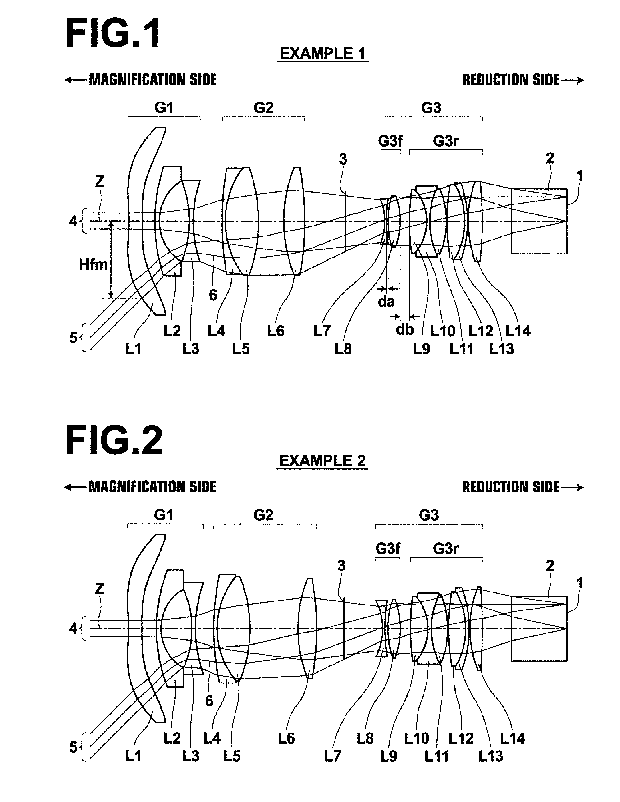
[0152]A lens structure diagram of a lens for projection in Example 1 and paths of rays are illustrated in FIG. 1. Since FIG. 1 has been described already, repetition of explanation will be omitted. FIG. 1 illustrates structure when projection distance is infinity.

[0153]The lens for projection in Example 1 has three group structure, in which first lens group G1 having negative refractive power, second lens group G2 having positive refractive power, and third lens group G3 having positive refractive power are arranged in this order from the magnification side. Further, the reduction side is telecentric. A glass block 2, which is assumed to be various kinds of filter, such as an infrared-ray-cut filter and a low-pass filter, a color combination prism and the like, is arranged toward the reduction side of third lens group G3. Further, an image display surface 1 of the light valve is arranged in contact with the reduction-side surface of the glass block 2. Further, an aperture 3 consisti...

example 2

[0172]FIG. 2 illustrates the lens structure of a lens for projection in Example 2 and paths of rays. The lens for projection in Example 2 has almost similar structure to the lens for projection in Example 1. Further, lenses that move during focusing are also similar. Table 4, Table 5 and Table 6 show basic lens data, variable surface distances, and aspherical surface coefficients, respectively, about the lens for projection in Example 2. FIG. 11, Sections A through H illustrate aberration diagrams of the lens for projection in Example 2. In the data about Example 2, projection distance is 123.93 when projection distance is finite distance. At this projection distance, the focal length of the entire system is 1.002, and an F-number is 1.70, and a full angle of view is 84.2°.

TABLE 4EXAMPLE 2 BASIC LENS DATASiRiDiNdjν dj*1−5.53130.54221.4910057.58*2−32.4926DD[2]35.68880.17821.6180063.3341.63011.26145−3.22950.14921.7725049.6064.8073DD[6]79.08920.13671.7552027.5182.84971.32791.7015441.24...

example 3

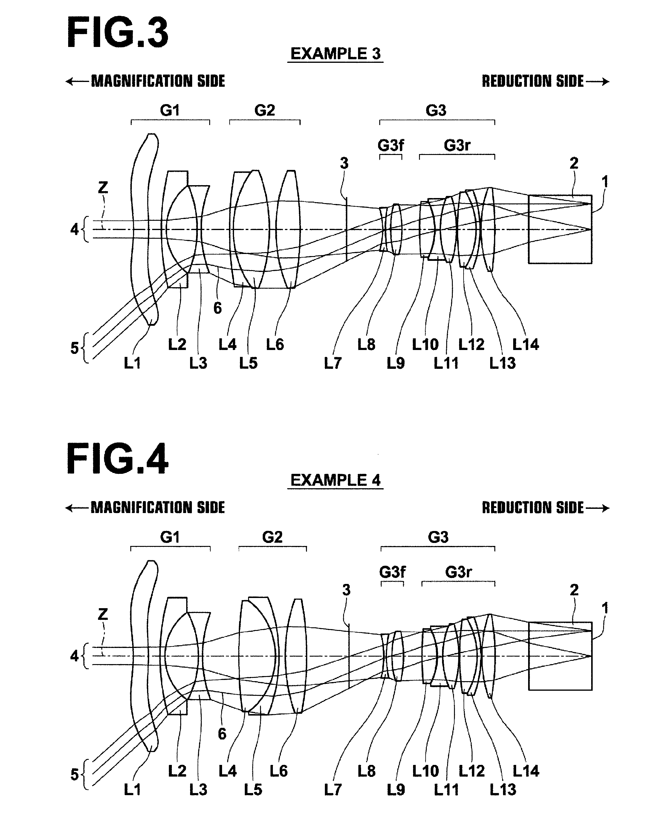
[0173]FIG. 3 illustrates the lens structure of a lens for projection in Example 3 and paths of rays. The lens for projection in Example 3 has almost similar structure to the lens for projection in Example 1. Further, lenses that move during focusing are also similar. Table 7, Table 8 and Table 9 show basic lens data, variable surface distances, and aspherical surface coefficients, respectively, about the lens for projection in Example 3. FIG. 12, Sections A through H illustrate aberration diagrams of the lens for projection in Example 3. In the data about Example 3, projection distance is 124.13 when projection distance is finite distance. At this projection distance, the focal length of the entire system is 1.003, and an F-number is 1.80, and a full angle of view is 79.0°.

TABLE 7EXAMPLE 3 BASIC LENS DATASiRiDiNdjν dj*1−3.22300.54311.4910057.58*2−4.8199DD[2]37.53800.17841.5891361.1441.71271.09285−3.40200.14731.7725049.6063.6823DD[6]710.19630.13261.7552027.5183.03541.30211.7015441.24...


PUM


Abstract

A lens for projection substantially consists of a negative first lens group, a positive second lens group and a positive third lens group in this order from a magnification side. A reduction side is telecentric, and a most magnification-side lens is an aspheric plastic lens. The third lens group consists of a negative front group and a positive rear group in this order from the magnification side with an air space therebetween. The front group consists of a negative lens and a positive lens in this order from the magnification side with an air space therebetween, and the air space being narrower than the air space between the front group and the rear group. Conditional formula (1): −0.7<fFG3/f<0.7 about front focus fFG3 of the third lens group and focal length f of an entire system is satisfied.

Description

CROSS-REFERENCE TO RELATED APPLICATIONS[0001]This application is a Continuation of PCT International Application No. PCT / JP2013 / 002512 filed on Apr. 12, 2013, which claims priority under 35 U.S.C. §119 (a) to Japanese Patent Application No. 2012-094480 filed on Apr. 18, 2012. Each of the above applications is hereby expressly incorporated by reference, in its entirety, into the present application.BACKGROUND OF THE INVENTION[0002]1. Field of the Invention[0003]The present invention relates to a lens for projection and a projection-type display apparatus. For example, the present invention relates to a lens for projection appropriate to magnify and project rays having video image information from a light valve onto a screen, and also to a projection-type display apparatus using the lens for projection.[0004]2. Description of the Related Art[0005]Conventionally, projection-type display apparatuses for magnifying and projecting images displayed on light valves, such as a liquid crystal...

Claims


Application Information

Patent Timeline
IPC IPC(8): G02B13/16G02B13/04H04N9/31G02B13/00
CPCG02B13/16H04N9/317G02B13/04G02B13/0045G02B13/18
Inventor NAGAHARA, AKIKONAGATOSHI, YUKIKO
Owner FUJIFILM CORP
Why Eureka
Try Eureka