Sheet determination apparatus using ultrasonic wave transmitting unit or reception unit

a sheet determination and ultrasonic wave technology, applied in the field of ultrasonic wave transmitting unit or reception unit, sheet determination apparatus, image forming apparatus, etc., can solve problems such as inability to operate normally

Active Publication Date: 2015-02-05
CANON KK
View PDF7 Cites 17 Cited by
  • Summary
  • Abstract
  • Description
  • Claims
  • Application Information

AI Technical Summary

Benefits of technology

[0007]In view of this, the present invention makes it difficult for a user to touch the vibrating member of at least one of a transmission unit and a reception unit for ultrasonic waves.

Problems solved by technology

Since an ultrasonic wave sensor transmits and receives ultrasonic waves due to a vibration member vibrating, if the vibration member is touched by a user, it cannot operate normally.

Method used


Image

  • Sheet determination apparatus using ultrasonic wave transmitting unit or reception unit
  • Sheet determination apparatus using ultrasonic wave transmitting unit or reception unit
  • Sheet determination apparatus using ultrasonic wave transmitting unit or reception unit

Examples


first embodiment

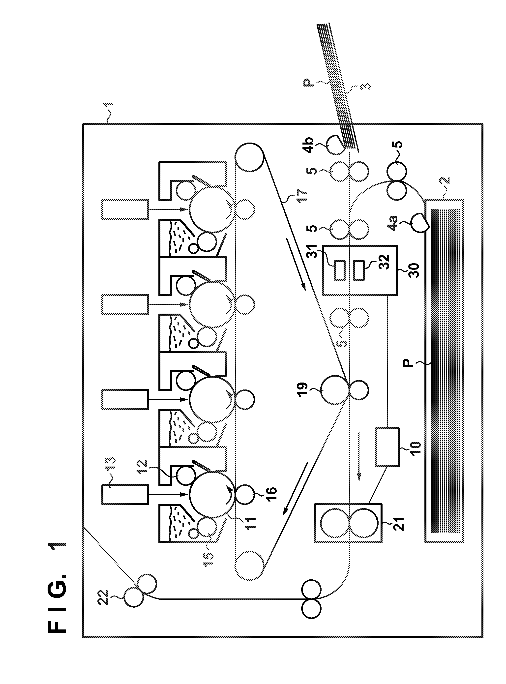
[0026]A sheet determination apparatus of the present embodiment can be used in an image forming apparatus such as a multi-function printer or a printer, for example. As an example of this, FIG. 1 shows an image forming apparatus 1 equipped with a sheet determination apparatus. In the image forming apparatus 1, multiple image forming units are arranged in a line, and toner images are transferred onto a sheet by an intermediate transfer member. In this example, the image forming units form an image using yellow, magenta, cyan, and black toner images respectively.

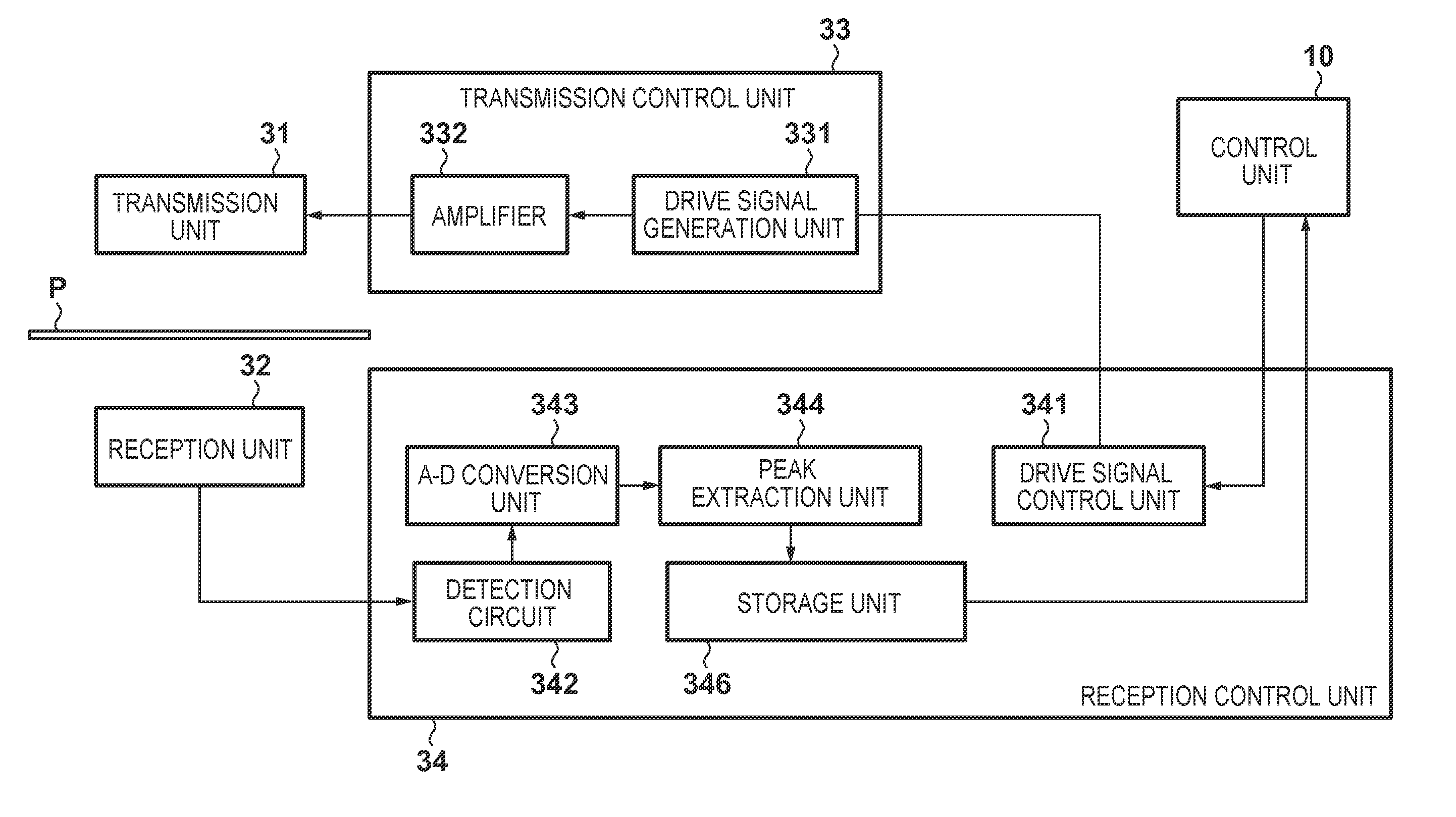
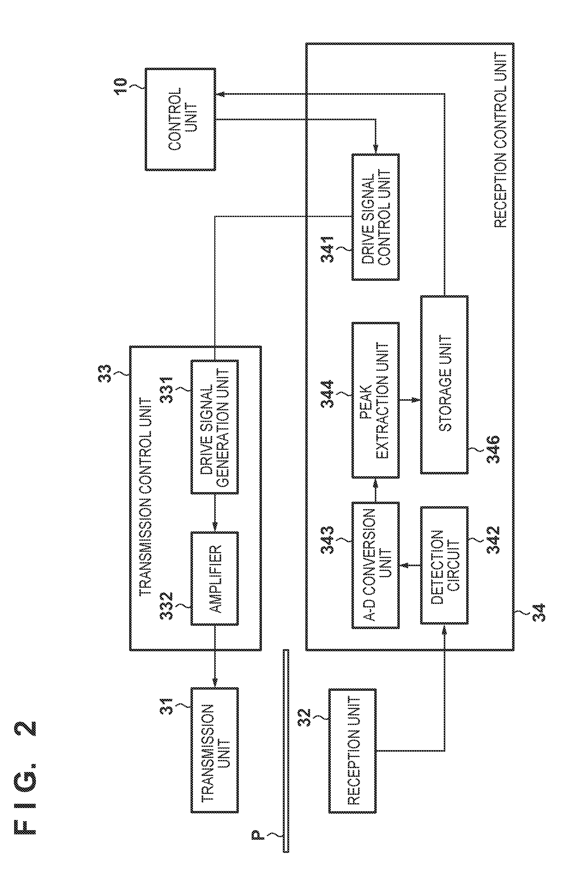
[0027]A sheet P is fed by feed rollers 4a and 4b that feed sheets from a feed cassette 2 or a feed tray 3. A conveyance roller 5 conveys the sheet P from the upstream side to the downstream side in the conveyance direction of the sheet P. An ultrasonic wave sensor 30 includes an ultrasonic wave transmission unit 31 and an ultrasonic wave reception unit 32 and detects ultrasonic waves corresponding to the type (grammage, thickn...

second embodiment

[0048]The first embodiment described an example in which the protection members 328 are arranged with respect to the ultrasonic wave reception unit 32. The second embodiment will describe an example in which protection members are arranged in both the ultrasonic wave transmission unit 31 and the ultrasonic wave reception unit 32. Note that configurations that are similar to those of the first embodiment such as that of the sheet determination apparatus are omitted so as to simplify the description.

[0049]The configurations of the ultrasonic wave transmission unit 31 and the ultrasonic wave reception unit 32 of the ultrasonic wave sensor 30 in the second embodiment are shown in FIGS. 7A to 7C. FIG. 7A is a perspective view of the ultrasonic wave transmission unit 31. FIG. 7B is a plan view of the ultrasonic wave transmission unit 31. FIG. 7C is a cross-sectional view taken along line A-A which shows the positional relationship between the ultrasonic wave transmission unit 31 and the u...

third embodiment

[0059]The first embodiment described a configuration in which the protection members 328 are arranged with respect to the ultrasonic wave reception unit 32. The second embodiment described a configuration in which protection members are arranged not only at the ultrasonic wave reception unit 32, but also at the ultrasonic wave transmission unit 31. The third embodiment will describe a configuration in which the protection member 318 is arranged only at the ultrasonic wave transmission unit 31. Note that the description of configurations similar to those of the first embodiment and the second embodiment will not be repeated.

[0060]The configuration of the ultrasonic wave transmission unit 31 of the ultrasonic wave sensor 30 will be described below with reference to FIGS. 9A to 9C. FIG. 9A is a perspective view of the ultrasonic wave transmission unit 31. FIG. 9B is a plan view of the ultrasonic wave transmission unit 31. FIG. 9C is a cross-sectional view taken along line A-A which sho...


PUM

PropertyMeasurementUnit
frequencyaaaaaaaaaa
wavelengthaaaaaaaaaa

Abstract

A protection member is arranged such that the distance from an opening plane of a reception guide to the center of the protection member is half of the distance from the opening plane of the reception guide to the surface of a reception vibration member. In other words, the arrangement position of the protection member is in the center between the opening plane of the reception guide and the surface of the reception vibration member. Accordingly, even if a protection member is arranged, a transmission coefficient is obtained that is equal to a transmission coefficient in the case where no protection member is present.

Description

BACKGROUND OF THE INVENTION[0001]1. Field of the Invention[0002]The present invention relates to an ultrasonic wave transmitting unit or reception unit, a sheet determination apparatus, and an image forming apparatus.[0003]2. Description of the Related Art[0004]Image forming apparatuses such as multi-function printers and laser printers use an ultrasonic wave sensor to determine the type of a sheet inside of the image forming apparatus and set image formation conditions such as transfer conditions and fixing conditions according to the determination result. Incidentally, there are cases where ultrasonic waves transmitted from a transmission unit are reflected multiple times and received by a reception unit. Reflection can occur due to a sheet, and also due to members in the periphery of the transmission unit and the reception unit, such as conveyance rollers and conveyance guides for conveying the sheet.[0005]Japanese Patent Laid-Open No. 2001-351141 proposes attaching sonic wave gu...

Claims


Application Information

Patent Timeline
Patent Type & Authority Applications(United States)
IPC IPC(8): G03G15/00G01N29/04G03G15/20G03G15/16
CPCG03G15/5029G01N29/04G01N29/11G01N2291/0237G01N2291/044G01N2291/048G03G2215/00324G03G2215/00611G01N29/2462G01N29/2468
Inventor ISHIDA, TSUTOMU
Owner CANON KK
Why Eureka
Try Eureka