

Connector
a technology of connecting rods and locking rods, applied in the direction of connection, electrical apparatus, coupling device connection, etc., can solve the problem of tripping of the locking rod, and achieve the effect of preventing excessive deflection of the locking rod
- Summary
- Abstract
- Description
- Claims
- Application Information
AI Technical Summary
Benefits of technology
Problems solved by technology
Method used
Image

Examples
Embodiment Construction
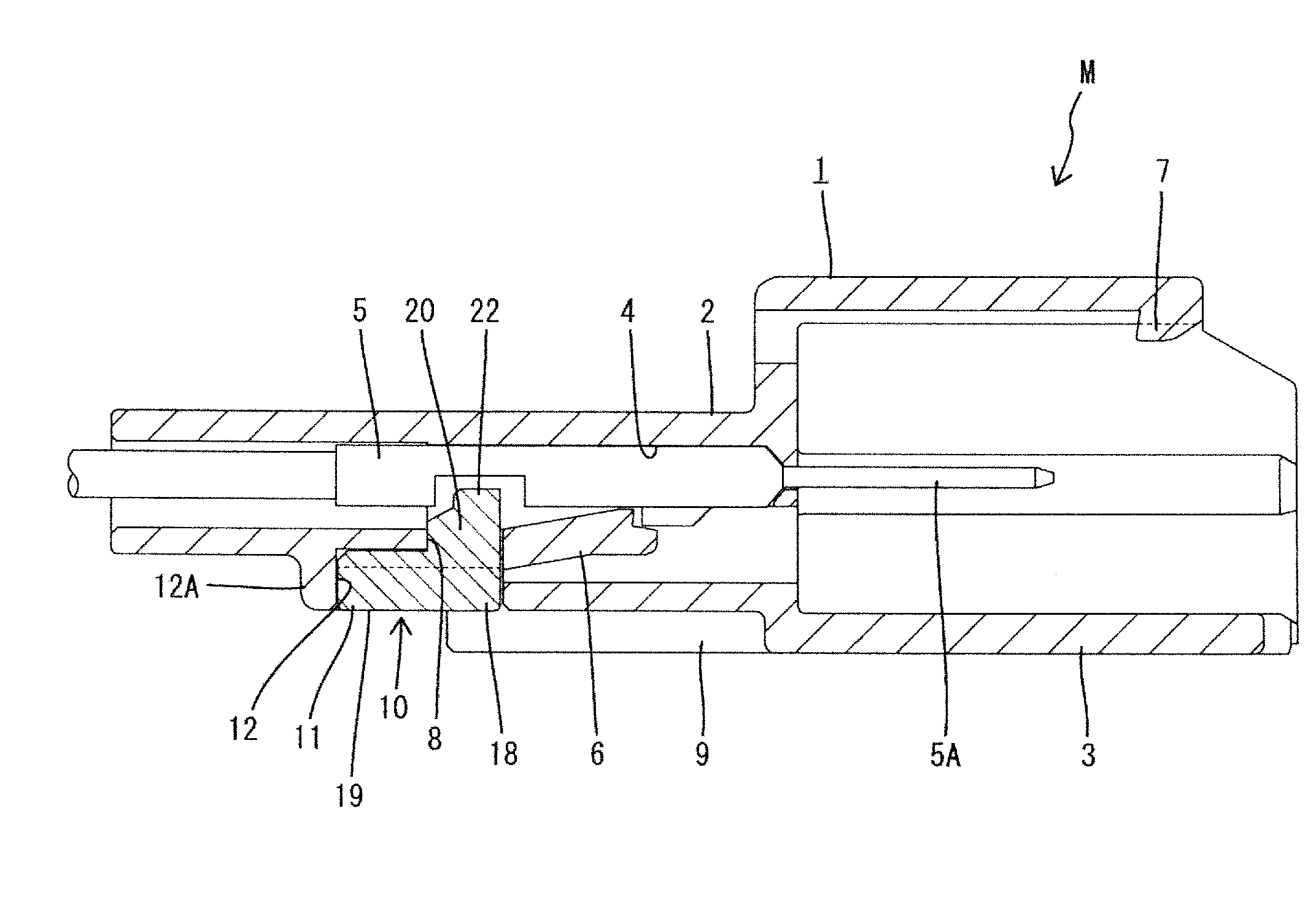
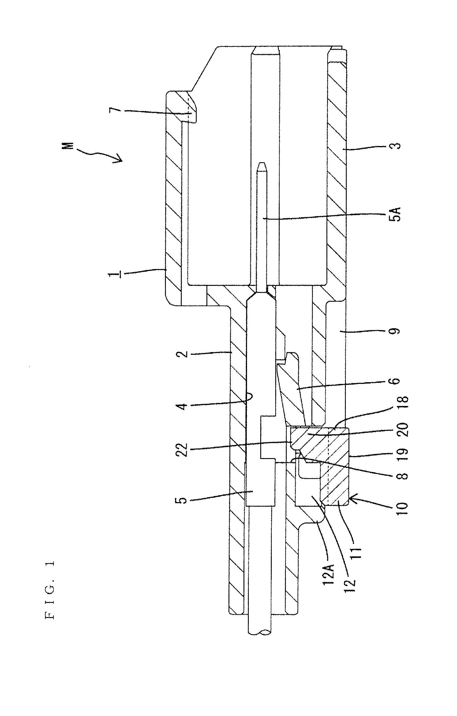
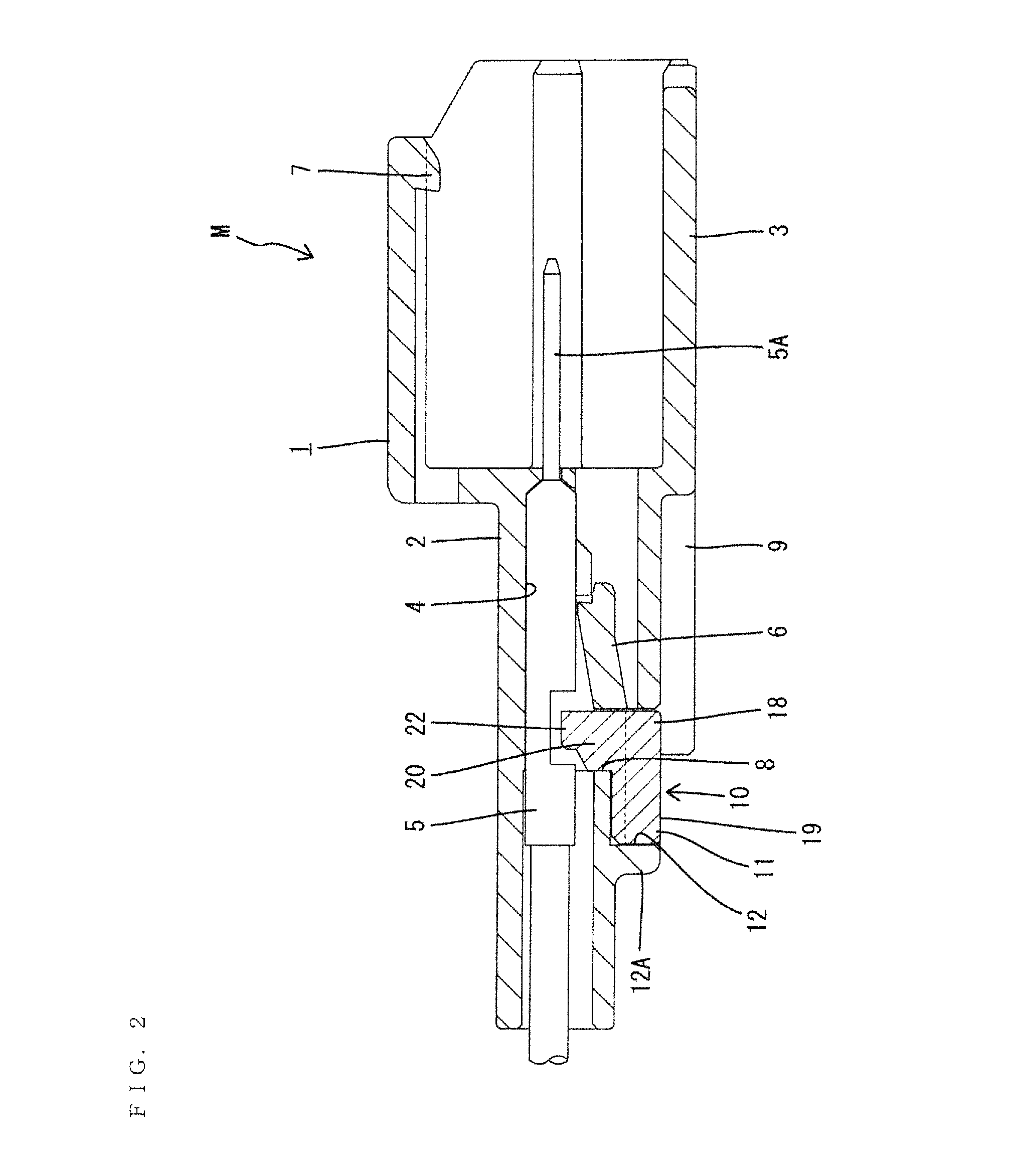
[0033]A specific embodiment of a connector of the invention is described with reference to the drawings. Note that, in the following description, front and rear ends in a connecting direction of male and female connectors are referred to as a “front” and a “rear” and a direction extending from a front to a back of the plane of FIG. 1 is referred to as a “width”.
[0034]A male connector in accordance with the invention is identified by the letter M and includes a male housing 1 made of synthetic resin. A rear end of the male housing 1 in a connecting direction to a female connector F defines a terminal accommodating portion 2, and a rectangular tubular receptacle 3 is formed at a front end. As shown in FIGS. 9 and 10, two cavities 4 are arranged side by side in the width direction in the terminal accommodating portion 2. Each cavity 4 is capable of accommodating a male terminal fitting 5, and a locking lance 6 is provided substantially in a central part in the cavity 4 for primarily lo...
PUM
 Abstract
Description
Claims
Application Information