Power conversion device

Active Publication Date: 2015-02-12
FUJI ELECTRIC CO LTD
View PDF5 Cites 11 Cited by
  • Summary
  • Abstract
  • Description
  • Claims
  • Application Information

AI Technical Summary

Benefits of technology

[0048]Further, in either of the power conversion devices, it is sufficient that current passes through only one bidirectional switch element when voltage of the 3-phase alternating current power supply is output. Consequently, a power conversion device to which the invention is applied is such that it is possible to prevent an increase in conduction loss that occurs when voltage of the 3-phase alternating current power supply is output.
[0049]Also, in each control period, the switching elements and bidirectional switch elements operate between two levels of voltage selected from four levels of voltage included in each voltage group. At the very least, the difference between the two levels of voltage does not exceed the sizes of the positive voltage and negative voltage of the direct curr

Problems solved by technology

Consequently, there is a problem in that there is an increase in switching loss caused by the switching elements Q1 to Q4 carrying out turn on/turn off operations.
Further, when the switching means K1 to K3 are configured of semiconductor elements, there is a problem in that conduction loss occurs due to current

Method used


Image

  • Power conversion device
  • Power conversion device
  • Power conversion device

Examples


first embodiment

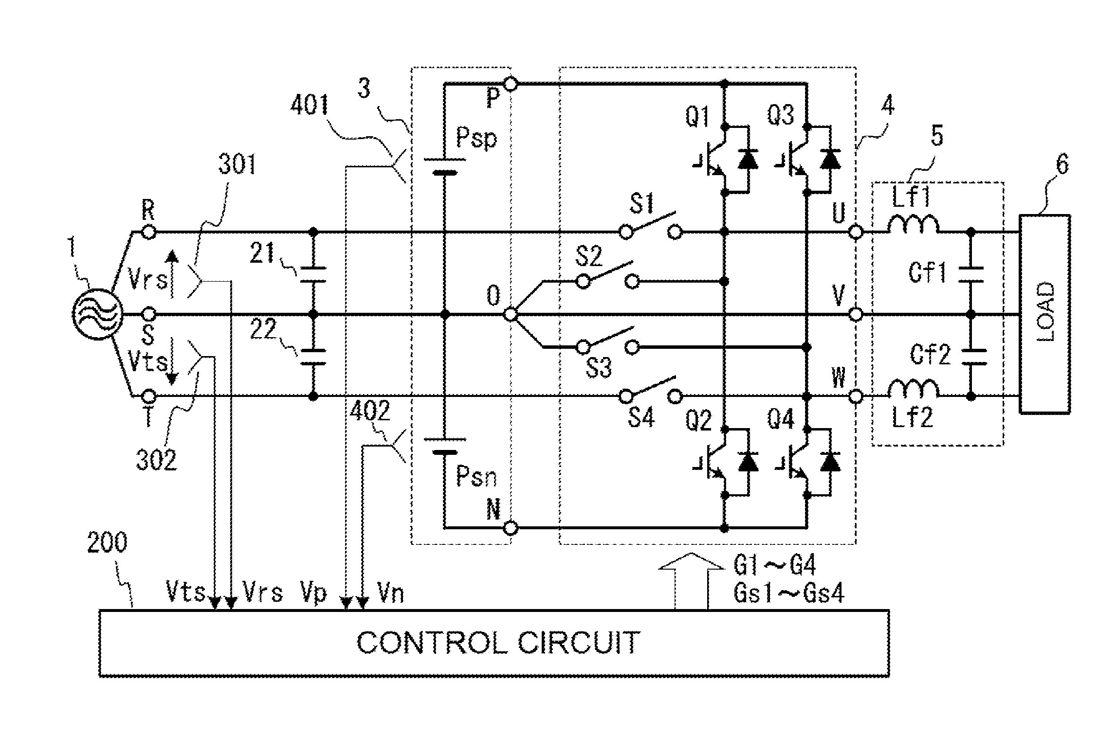
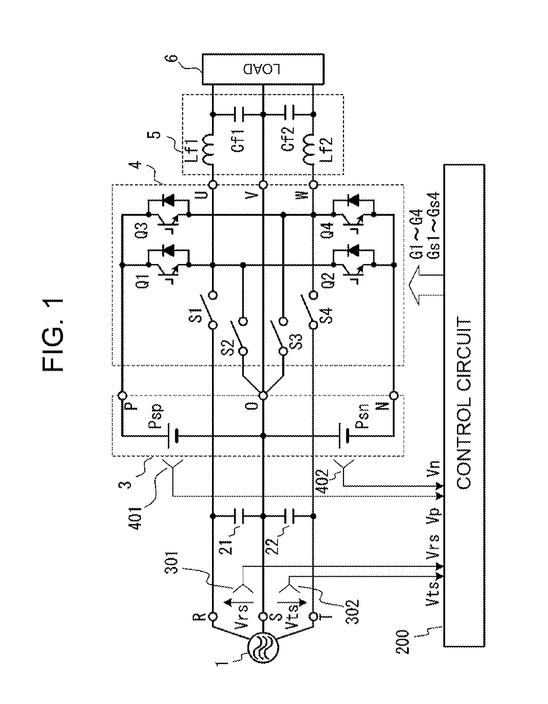
[0070]FIG. 1 is a diagram for illustrating the power conversion device according to the invention. The power conversion device is such that a 3-phase alternating current power supply 1 and a load 6 are V-connected, and a predetermined 3-phase alternating current voltage is generated using the voltage of the 3-phase alternating current power supply 1 and a direct current voltage generated from this voltage.

[0071]In the drawing, reference sign 1 is the 3-phase alternating current power supply, reference signs 21 and 22 are capacitors, reference sign 3 is a direct current power supply series circuit, reference sign 4 is an inverter circuit, reference sign 5 is a filter circuit, reference sign 6 is the load, and reference sign 200 is a control circuit.

[0072]The 3-phase alternating current power supply 1 outputs an R-phase voltage, an S-phase voltage, and a T-phase voltage from a terminal R (first terminal), a terminal S (third terminal), and a terminal T (second terminal) respectively. ...


PUM


Abstract

A power conversion device able to supply a constant load voltage even when the voltage of a 3-phase alternating current power supply fluctuates. A series circuit formed of switching element Q1 and switching element Q2 and a series circuit formed of switching element Q3 and switching element Q4 are connected to both ends of direct current power supply series circuit 3 formed of direct current power supply Psp and direct current power supply Psn, a bidirectional switch element S1 is connected between alternating current output terminals U and R, a bidirectional switch element S2 is connected between alternating current output terminal U and neutral terminal O, a bidirectional switch element S3 is connected between alternating current output terminal W and neutral terminal O, a bidirectional switch element S4 is connected between alternating current output terminal W and terminal T, and alternating current output terminals V and terminal S are connected.

Description

CROSS-REFERENCE TO RELATED APPLICATIONS[0001]This application is a continuation application of International Application number PCT / JP2012 / 004393, filed on Jul. 6, 2012 and designating the United States. Furthermore, this application claims the benefit of foreign priority of Japanese application 2012-083935, filed on Apr. 2, 2012. The disclosures of these earlier applications are hereby incorporated herein by reference.TECHNICAL FIELD[0002]The present invention relates to a power conversion device that generates a predetermined 3-phase alternating current voltage using the voltages of a 3-phase alternating current power supply and a direct current power supply. More specifically, the invention relates to a momentary voltage drop compensation device and uninterruptible power supply device wherein it is possible to supply a stable voltage to a load even when a 3-phase alternating current power supply voltage fluctuation or a 3-phase alternating current power supply interruption occurs...

Claims


Application Information

Patent Timeline
IPC IPC(8): H02J9/00H02M1/14H02M7/537
CPCH02J9/00H02M1/14H02M7/537H02M5/297H02M11/00H02M1/10H02M5/4585H02M7/483H02J9/063H02M1/0095
Inventor FUJITA, SATORUYAMADA, RYUJI
Owner FUJI ELECTRIC CO LTD
Why Eureka
Try Eureka