Method and apparatus to diagnose current sensor polarities and phase associations for a three-phase electric power system
- Summary
- Abstract
- Description
- Claims
- Application Information
AI Technical Summary
Benefits of technology
Problems solved by technology
Method used
Image

Examples
example
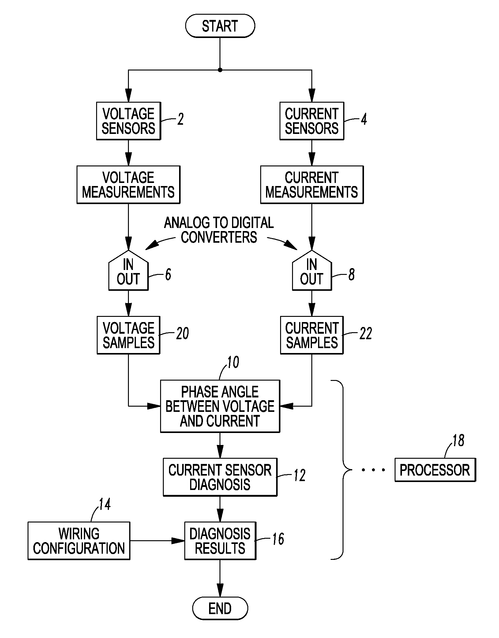
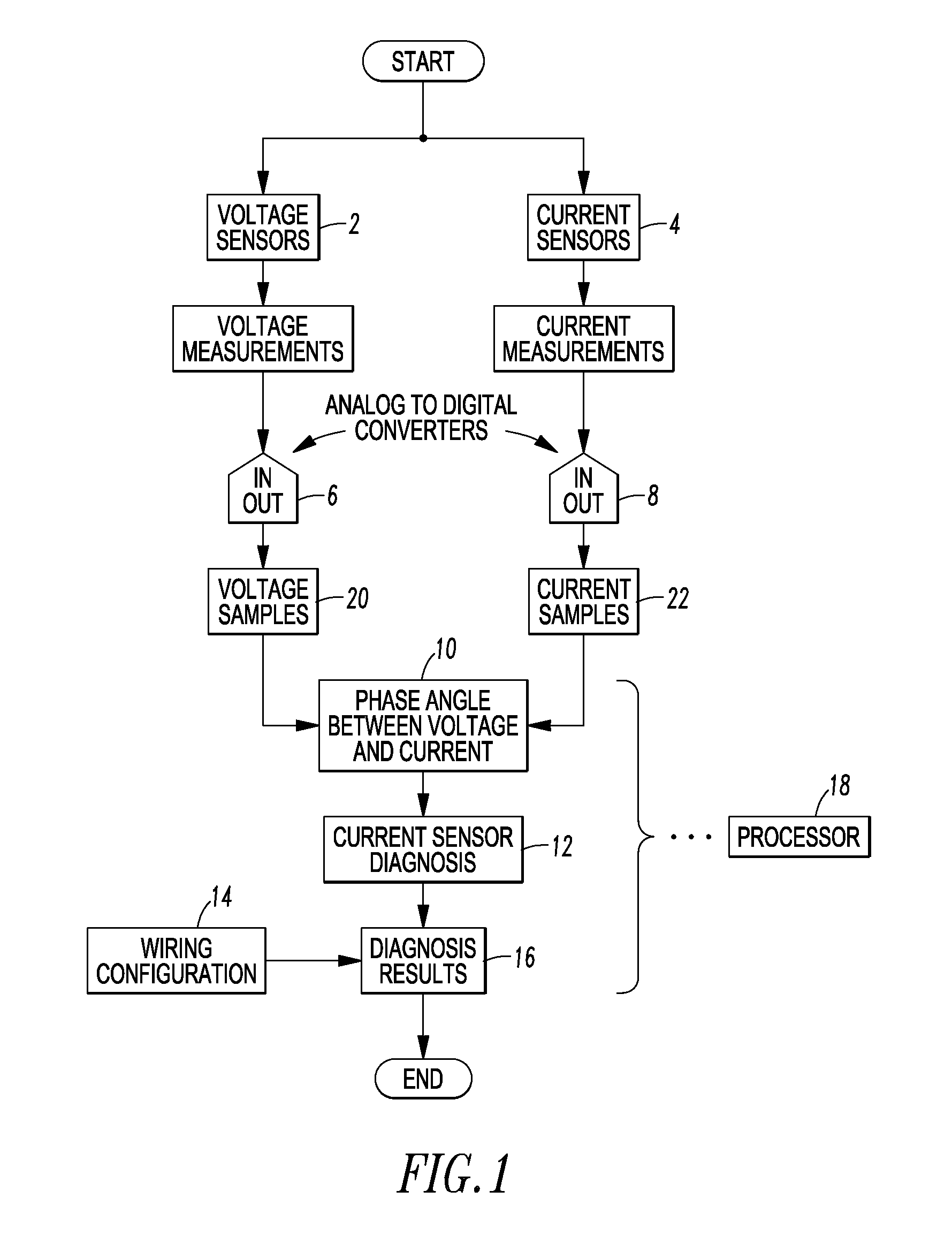
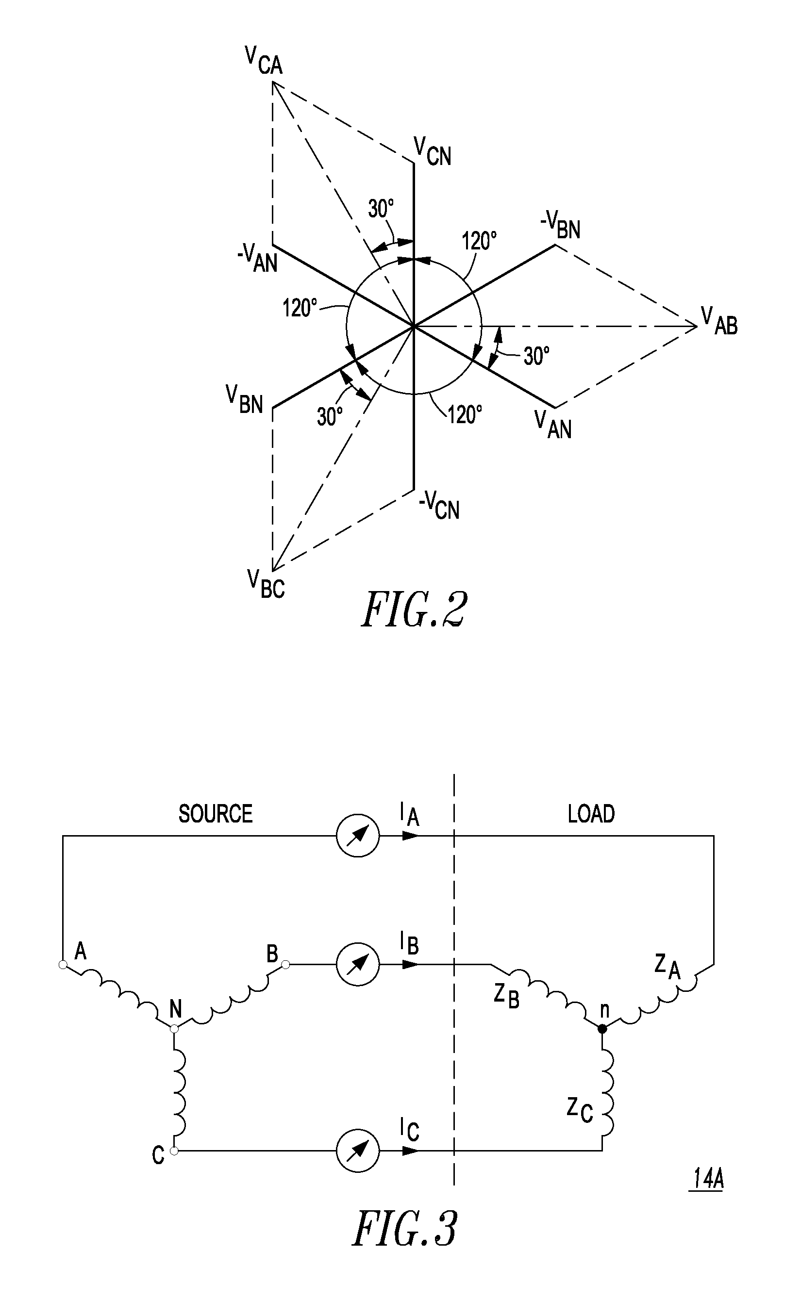
[0109]An example in connection with FIG. 18 is for a 3-phase 4-wire wye wiring configuration (FIG. 3). In this example, the current sensor intended to measure phase A current is mistakenly wired to the phase C current-carrying conductor with a normal polarity; the current sensor intended to measure phase B current is mistakenly wired to the phase A current-carrying conductor with a reversed polarity; and the current sensor intended to measure phase C current is mistakenly wired to the phase B current-carrying conductor with a normal polarity. As a result, the current sensor diagnosis yields the following results according to Table II: φA indicated IC, φB indicated −IA, and φC indicated IB.
[0110]Using the above diagnosis result, and following the flowchart in FIG. 18, because φB indicated −IA, the first logical test “φB indicated −IA or −IA” is true, and the first corrective action to “Swap Current Sensors A and B” needs to be taken. Next, because φC indicated IB, the logical test “φ...
PUM
 Abstract
Description
Claims
Application Information
 - R&D Engineer
- R&D Manager
- IP Professional
- Industry Leading Data Capabilities
- Powerful AI technology
- Patent DNA Extraction
Browse by: Latest US Patents, China's latest patents, Technical Efficacy Thesaurus, Application Domain, Technology Topic.
© 2024 PatSnap. All rights reserved.Legal|Privacy policy|Modern Slavery Act Transparency Statement|Sitemap