Touch panel and liquid crystal display device having the touch panel

a liquid crystal display device and touch panel technology, applied in the field of touch panel and display device having the touch panel, can solve the problem of deteriorating the visual quality of an image to be displayed through the touch panel

Active Publication Date: 2015-02-12
JAPAN DISPLAY INC
View PDF5 Cites 20 Cited by
  • Summary
  • Abstract
  • Description
  • Claims
  • Application Information

AI Technical Summary

Benefits of technology

[0008]The present invention has been made in view of the above circumstances, and therefore aims at preventing the visibility of the image displayed through the touch panel from being deteriorated.
[0011](3) According to the present invention, in the touch panel according to the item (1) or (2), the planar view shape of the polygons may be viewed as a circle by increasing the number of corners.

Problems solved by technology

This results in a risk that the visibility of an image to be displayed through the touch panel is deteriorated.

Method used


Image

  • Touch panel and liquid crystal display device having the touch panel
  • Touch panel and liquid crystal display device having the touch panel
  • Touch panel and liquid crystal display device having the touch panel

Examples


Embodiment Construction

[0030]Hereinafter, a touch panel and a display device according to this embodiment will be described with the example of a liquid crystal display device 1 with reference to the accompanying drawings. For facilitation of understanding the characteristics, the drawings referred to in the following description may illustrate characteristic portions in an enlarged manner for convenience, and size ratios of the respective components are not always identical with actual size ratios. Also, materials and the like exemplified in the following description are exemplary, and the respective components may be made of materials different from the exemplary materials, and can be changed without departure from the spirit thereof.

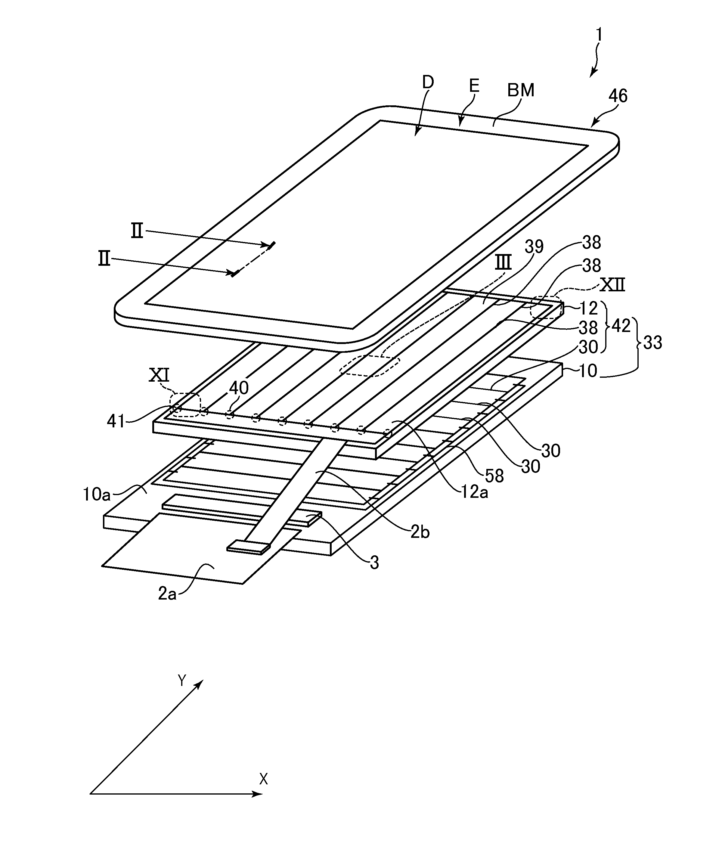
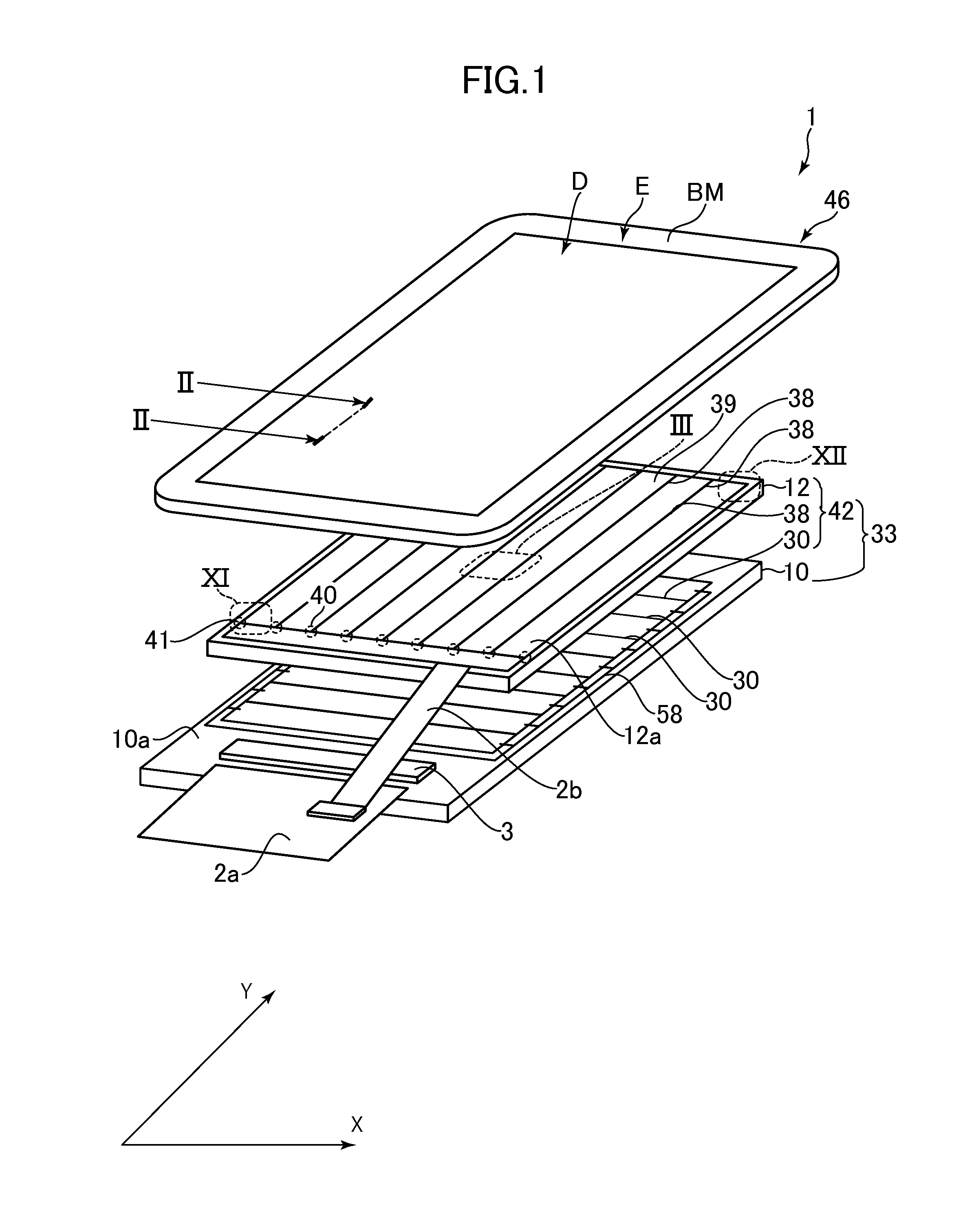
[0031]FIG. 1 is an exploded perspective view of the liquid crystal display device 1 having a touch panel according to an embodiment of the present invention. As illustrated in FIG. 1, the liquid crystal display device 1 includes a liquid crystal display panel 33, and a fron...


PUM

PropertyMeasurementUnit
radiusaaaaaaaaaa
radiusaaaaaaaaaa
radius d1aaaaaaaaaa

Abstract

A touch panel includes plural scanning electrodes, plural detection electrodes that are formed to intersect with the plural scanning electrodes, one or a plurality of layers being disposed between the plural detection electrodes and the plural scanning electrodes, plural holes that are arrayed apart from each other on each of the plural detection electrodes, and shaped into polygons each shaped to have five or more corners in a plan view, and plural dummy electrodes that are formed between the respective adjacent detection electrodes, made of the same material as that of the detection electrode, and electrically isolated from each other, in which the plural dummy electrodes are shaped into the polygons in a plan view.

Description

CROSS-REFERENCE TO RELATED APPLICATION[0001]The present application claims priority from Japanese application JP2013-165819 filed on Aug. 9, 2013, the content of which is hereby incorporated by reference into this application.BACKGROUND OF THE INVENTION[0002]1. Field of the Invention[0003]The present invention relates to a touch panel and a display device having the touch panel.[0004]2. Description of the Related Art[0005]In recent years, a touch panel that detects a position which is touched with a finger, a dedicated pen or the like has been developed. As the touch panel of this type, for example, a capacitance type touch sensor has been known which detects a change in capacitance of a portion that is subjected to a touch pressing operation (hereinafter referred to as “touch”). In a touch panel of an in-cell touch panel in which common electrodes in a liquid crystal display panel of an IPS (In-Plane Switching) system are used as scanning electrodes for touch detection, the scannin...

Claims


Application Information

Patent Timeline
Patent Type & Authority Applications(United States)
IPC IPC(8): G02F1/1333G02F1/1343
CPCG02F1/134309G02F1/13338G06F3/0412G06F3/0443G06F3/0445G02F1/133345G02F1/134363G02F1/13439G02F1/1368G02F2201/123G06F2203/04102G06F2203/04103G06F2203/04107G02F1/136218
Inventor SEKIGUCHI, SHINJI
Owner JAPAN DISPLAY INC
Why Eureka
Try Eureka