Timing System and Method

a timing system and time-based technology, applied in image data processing, instruments, character and pattern recognition, etc., can solve the problems of complex setup, unsuitable for all events, and inconvenient to use, so as to improve the image quality

Active Publication Date: 2015-02-12
MOBII SYST
View PDF3 Cites 5 Cited by
  • Summary
  • Abstract
  • Description
  • Claims
  • Application Information

AI Technical Summary

Benefits of technology

[0019]Generally, the system further includes a lighting system for illuminating the glyph to improve the images captured by the at least one camera. Preferably, the lighting system emits UV or infrared light and at least one camera includes a UV or infra-red filter.
[0038]Optionally, the timing method further includes the step of illuminating the glyph to improve the quality of the images. Preferably, the glyph is illuminated in UV or infrared light and at least one camera includes a UV or infrared filter.

Problems solved by technology

However, RFID systems have their drawbacks: they are expensive, complicated to set up; and not suitable for all events (such as canoeing).
However, such systems do not accurately record the time that the glyph (or an object associated with the glyph) passes a predetermined point or line.

Method used


Image

  • Timing System and Method
  • Timing System and Method
  • Timing System and Method

Examples


Embodiment Construction

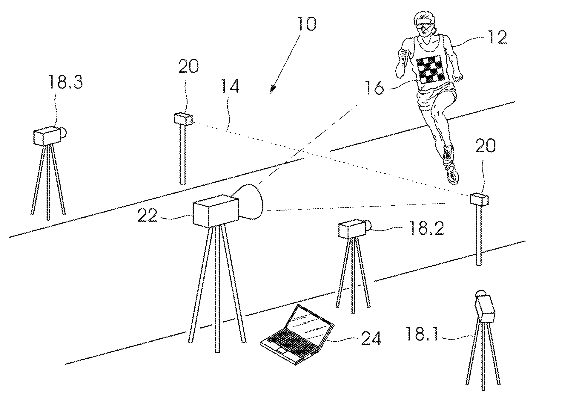
[0054]With reference to FIG. 1, according to a first aspect of the invention a timing system 10 is provided for determining the time that an object 12 crosses a predetermined point or line 14.

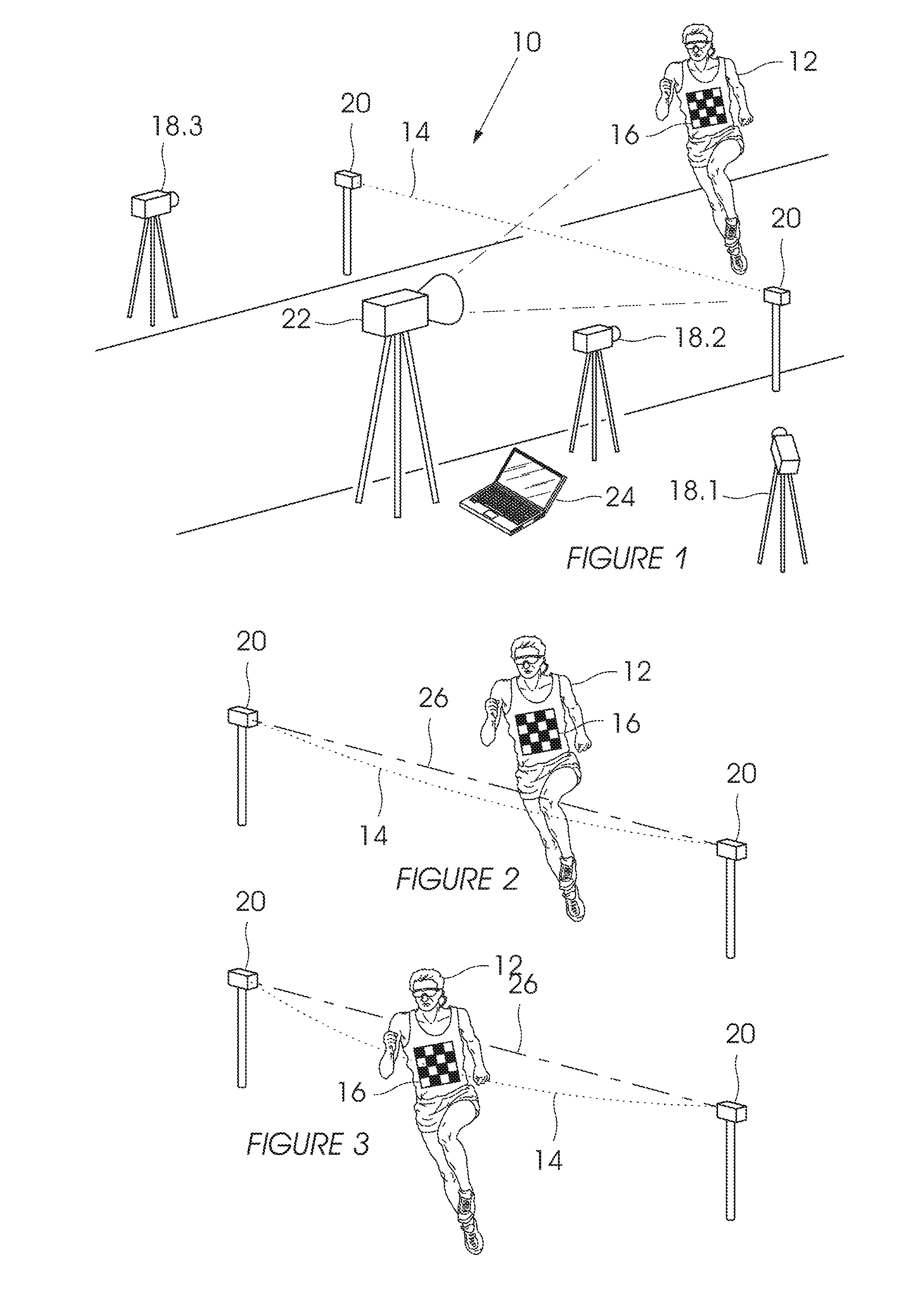
[0055]The object could be a motor vehicle, runner, cyclist, kayaker, canoeist, boat or any other mobile object. By way of example, FIGS. 1 to 3 show the object 12 in the form of a runner nearing the end of a running race.

[0056]The timing system 10 requires the runner 12 to wear a glyph 16—a unique image designed to be recognised easily by image recognition software. FIGS. 1 to 3 shows the glyph 16 attached to the runner's 12 bib. However, this could be associated with any mobile object in any other way, such as being stuck or painted directly onto a motor vehicle, placed on the front of a mountain bike, etc. Furthermore, it will be appreciated that the glyph 16 could be any other type of unique identifier, such as the race number on a bib, or the custom designed colour print of “43” on a race v...


PUM


Abstract

A timing system that includes a glyph associated with an object to be timed and at least one camera for capturing images of the glyph or associated object. A computer generates a virtual line, associates the virtual line with at least one of the images, and determines when the glyph or associated object intersects, crosses or has crossed the virtual line. A database records the identity of the glyph and the time that the glyph or associated object intersected or crossed the virtual line. The invention also relates to a related method for determining the time a glyph or object associated therewith passes a predetermined point or line.

Description

BACKGROUND[0001]The present invention relates to a timing system and method using video images to determine the time an object crosses a predetermined point or line.[0002]Various systems for timing participants in a race and vehicles passing under a toll system are known.[0003]Race events often employ RFID systems for recording the time that participants cross the finish line. However, RFID systems have their drawbacks: they are expensive, complicated to set up; and not suitable for all events (such as canoeing).[0004]Horse racing has adopted image recording technology. A camera is setup in-line with the finish line and a line corresponding with the finish line is superimposed on the image.[0005]Time keepers use these images to determine the frame (and therefore the time) in which each horse crosses the finish line. However, the time keepers must then manually identify each horse and assign a finishing time to it.[0006]Movement recording systems using glyphs are common in vehicle ma...

Claims


Application Information

Patent Timeline
Patent Type & Authority Applications(United States)
IPC IPC(8): G06T7/00
CPCG06T7/0044G06T2207/30204G06T2207/30221G06T7/74
Inventor BARRETT, RODERICKBARRETT, BRENDANTHACKER, MICHAEL DONBURLS, PATRICK ALEX
Owner MOBII SYST
Why Eureka
Try Eureka