
Image processing apparatus, image processing method, and imaging apparatus

Active Publication Date: 2015-02-12
CANON KK
View PDF6 Cites 73 Cited by
  • Summary
  • Abstract
  • Description
  • Claims
  • Application Information

AI Technical Summary

Benefits of technology

The present invention aims to prevent image quality degradation when using a depth map for image processing. The invention helps to maintain the quality of the image while applying various image processing techniques. This results in better overall performance and a higher level of user satisfaction.

Problems solved by technology

However, there are regions where the correspondence cannot be found such as regions without a texture and regions having the same texture.
In this way, because of causes peculiar to the respective systems, in some cases, a depth map cannot be acquired or the accuracy of a depth map is not high.
Therefore, when it is attempted to generate an image having a shallow depth of field using depth information or when image restoration is performed using the depth information as in Patent Literature 1, a marked sense of discomfort occurs in an image in a region where a highly accurate depth map cannot be acquired.
Even when an ideal depth map can be acquired, there is still a problem.

Method used


Image

  • Image processing apparatus, image processing method, and imaging apparatus
  • Image processing apparatus, image processing method, and imaging apparatus
  • Image processing apparatus, image processing method, and imaging apparatus

Examples


first embodiment

[0027]A specific embodiment of the present invention is explained below with reference to the drawings. An imaging apparatus according to this embodiment is an imaging apparatus capable of simultaneously acquiring a depth map and a viewing image. The imaging apparatus according to this embodiment includes two imaging systems and acquires a depth map in a stereo system. However, the scope of the invention is not limited to examples shown in the figures in the explanation of the embodiment.

[0028]

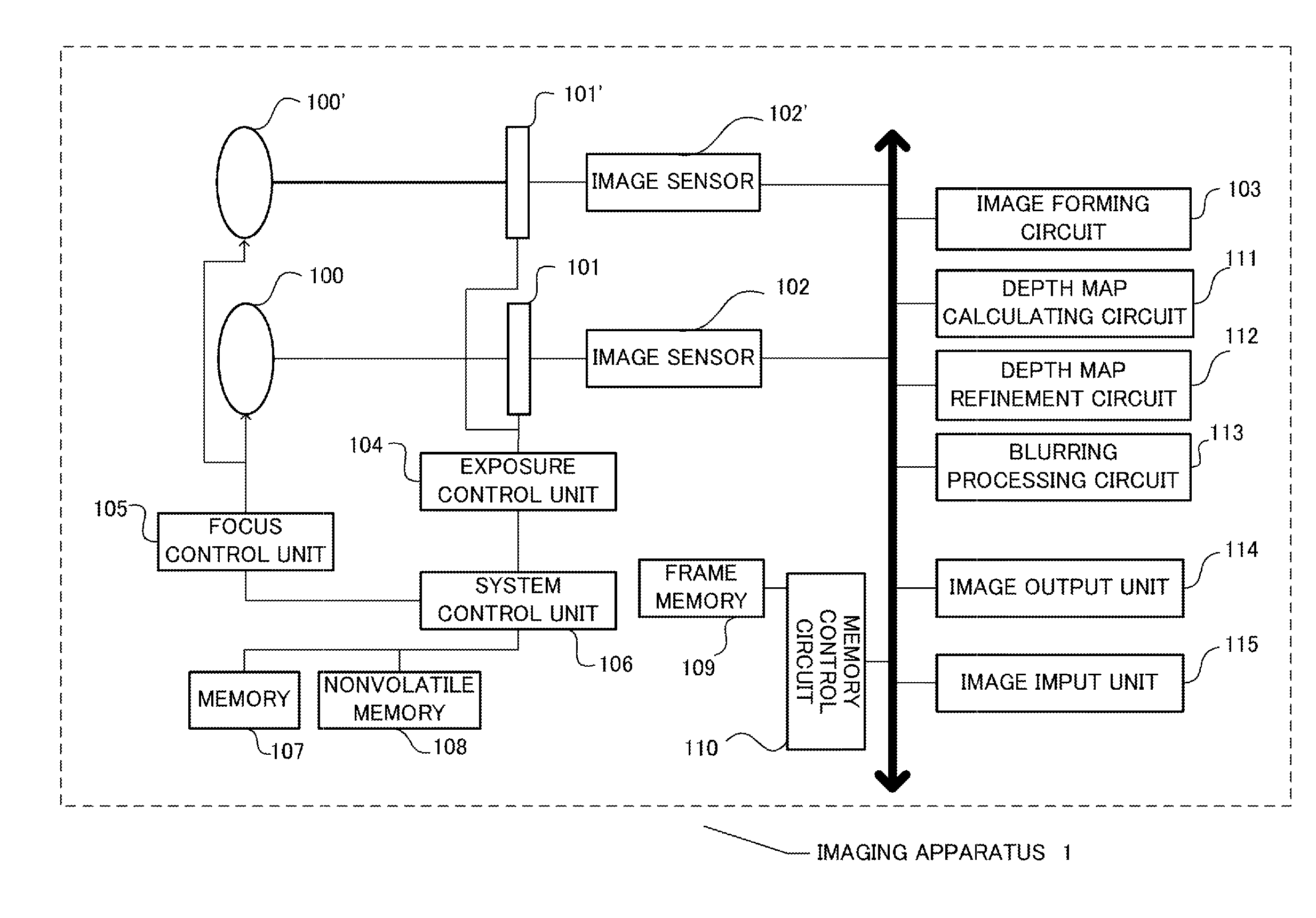
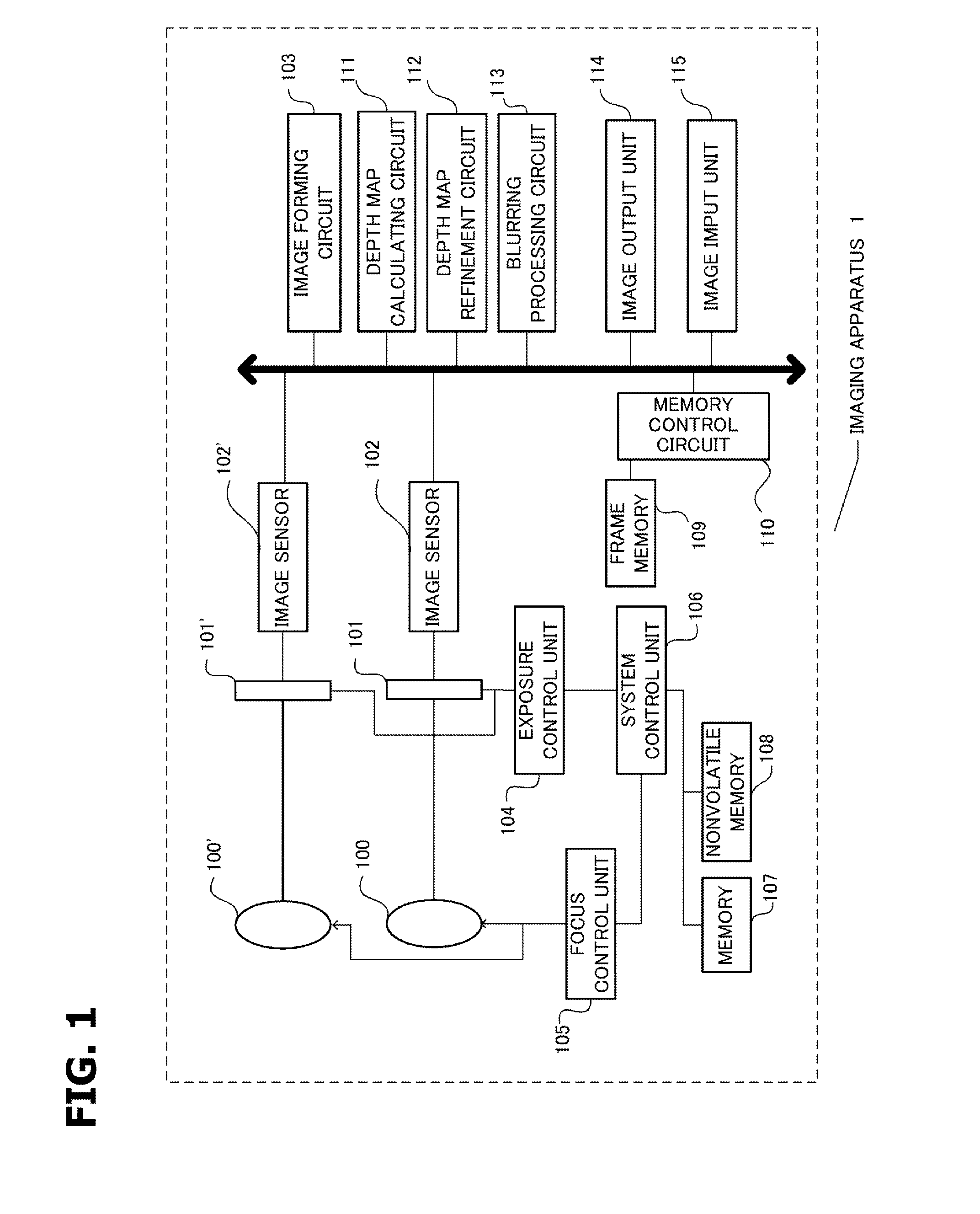
[0029]FIG. 1 schematically shows the configuration of an imaging apparatus 1 according to this embodiment. The imaging apparatus 1 includes two imaging systems. Optical systems 100 and 100′ respectively include a plurality of lenses for guiding light from an object (object light) to image sensors 102 and 102′. Exposure control members 101 and 101′ include diaphragms and shutters. The object light made incident via the optical systems 100 and 100′ are made incident on the image sensors 102 and ...

second embodiment

[0061]A second embodiment is an imaging apparatus in which a DFD system is used as a depth map acquiring system. In the following explanation, image processing for reducing a depth of field is applied to a viewing image using a depth map. However, as in the first embodiment, this embodiment can also be applied to image restoration processing, super-resolution processing, and the like.

[0062]The configuration of the imaging apparatus in this embodiment is shown in FIG. 7. Among reference numerals in FIG. 7, the reference numerals same as the reference numerals in the configuration diagram of FIG. 1 denote the same components. Therefore, only different components are explained.

[0063]A depth map calculating circuit 701 shown in FIG. 7 calculates a depth map in the DFD system. A depth map refinement circuit 702 is a circuit that corrects the depth map calculated by the depth map calculating circuit 701.

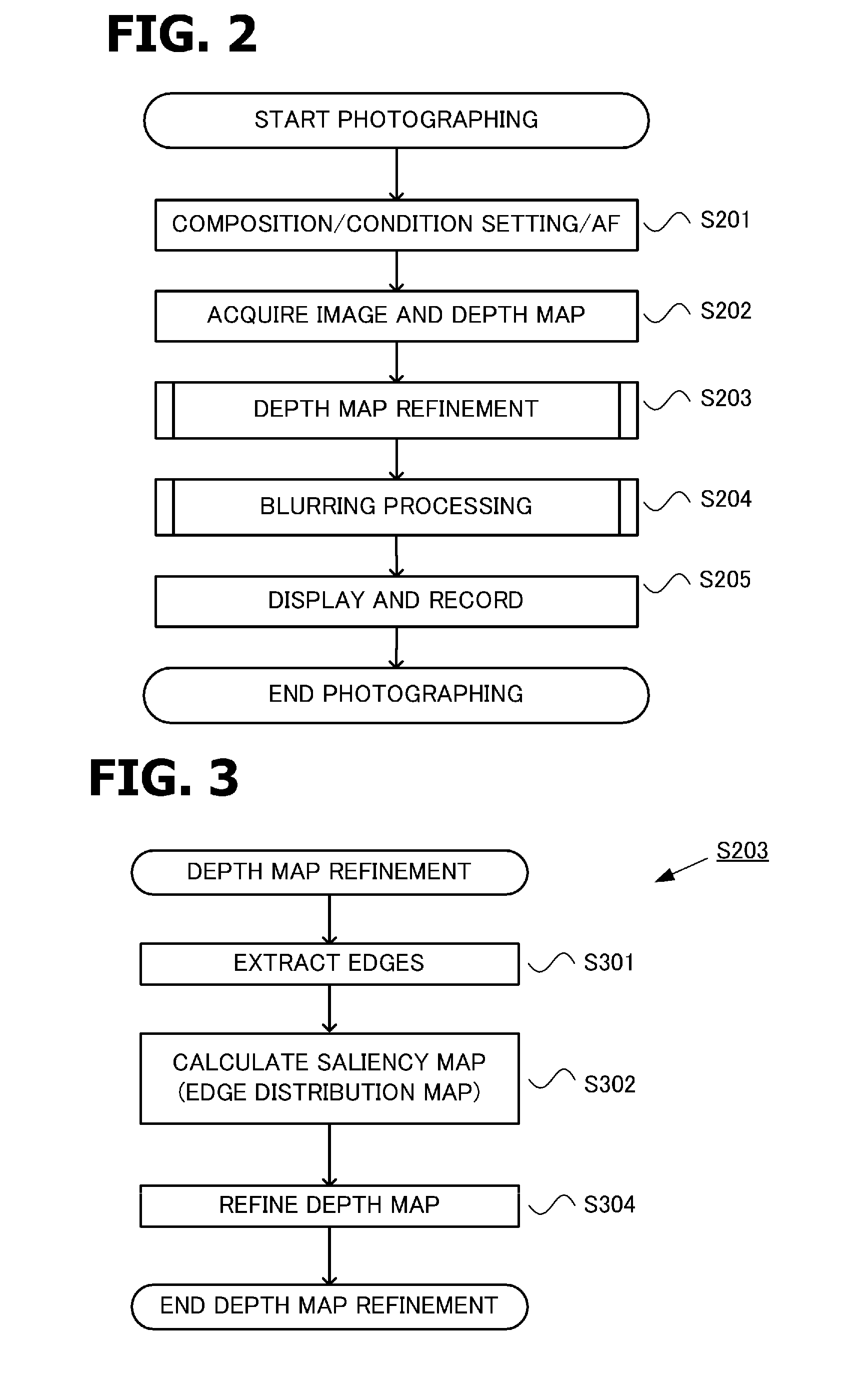
[0064]A flow of the processing in this embodiment is explained with reference to a flo...


PUM


Abstract

An image processing apparatus comprising: an image acquisition unit configured to acquire an image; a depth map acquisition unit configured to acquire a depth map corresponding to the image; a refinement unit configured to detect a saliency region from the image and to refine the depth map on the basis of the saliency region, the saliency region being a region on which a person tends to focus; and an image processing unit configured to apply image processing to the image using the depth map refined by the refinement unit.

Description

BACKGROUND OF THE INVENTION[0001]1. Field of the Invention[0002]The present invention relates to an image processing apparatus, and specifically relates to an image processing apparatus that applies image processing to a viewing image using depth information.[0003]2. Description of the Related Art[0004]In recent years, an imaging apparatus has been developed that is capable of simultaneously acquiring a viewing image and a depth map representing a depth to a scene being photographed. As a system for acquiring the depth map, there are a plurality of systems. For example, there is a stereo system for acquiring images from a plurality of visual point positions and calculating a depth on the basis of the principle of triangulation using a parallax calculated from a correspondence relation among pixels in the images. There are also a depth from defocus (DFD) system and a depth from focus (DFF) system for analyzing blurring states of a plurality of images acquired under shooting condition...

Claims


Application Information

Patent Timeline
IPC IPC(8): G06K9/46G06T7/00
CPCG06T7/0051G06K9/4676G06T2207/10004G06T2207/10028G06T2207/20192G06T7/529H04N13/128G06T5/50G06T5/73
Inventor TAKAHASHI, TAKAHIROISHIHARA, KEIICHIROKOMATSU, SATORUTANAKA, SHIN
Owner CANON KK
Learn More