Chamfering tool

a tool and chamfering technology, applied in the field of chamfering tools, can solve the problems of user difficulty in initial alignment of the edge of the work piece with the gage, the blade and the gage must be adjusted, etc., and achieve the effect of easy adjustment and replacement of the blad

Inactive Publication Date: 2015-02-19
STANLEY WORKS THE
View PDF3 Cites 3 Cited by
  • Summary
  • Abstract
  • Description
  • Claims
  • Application Information

AI Technical Summary

Benefits of technology

[0017]Preferably the blade clamp comprises a tool free knob for clamping t

Problems solved by technology

A problem with the plane is that the blade and the gage must be adjusted before chamfering a corner of a panel.
The

Method used


Image

  • Chamfering tool
  • Chamfering tool
  • Chamfering tool

Examples


Embodiment Construction

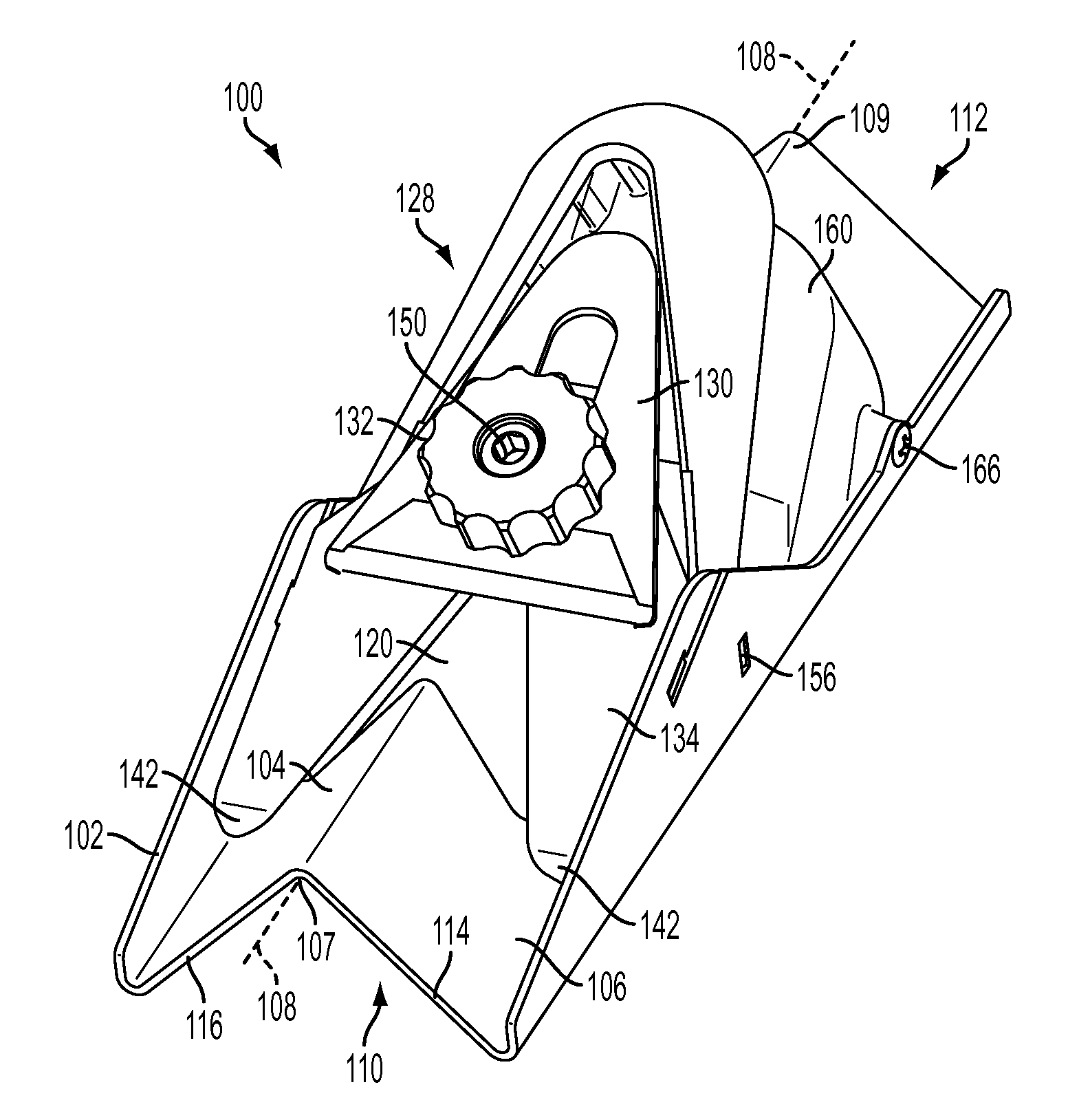
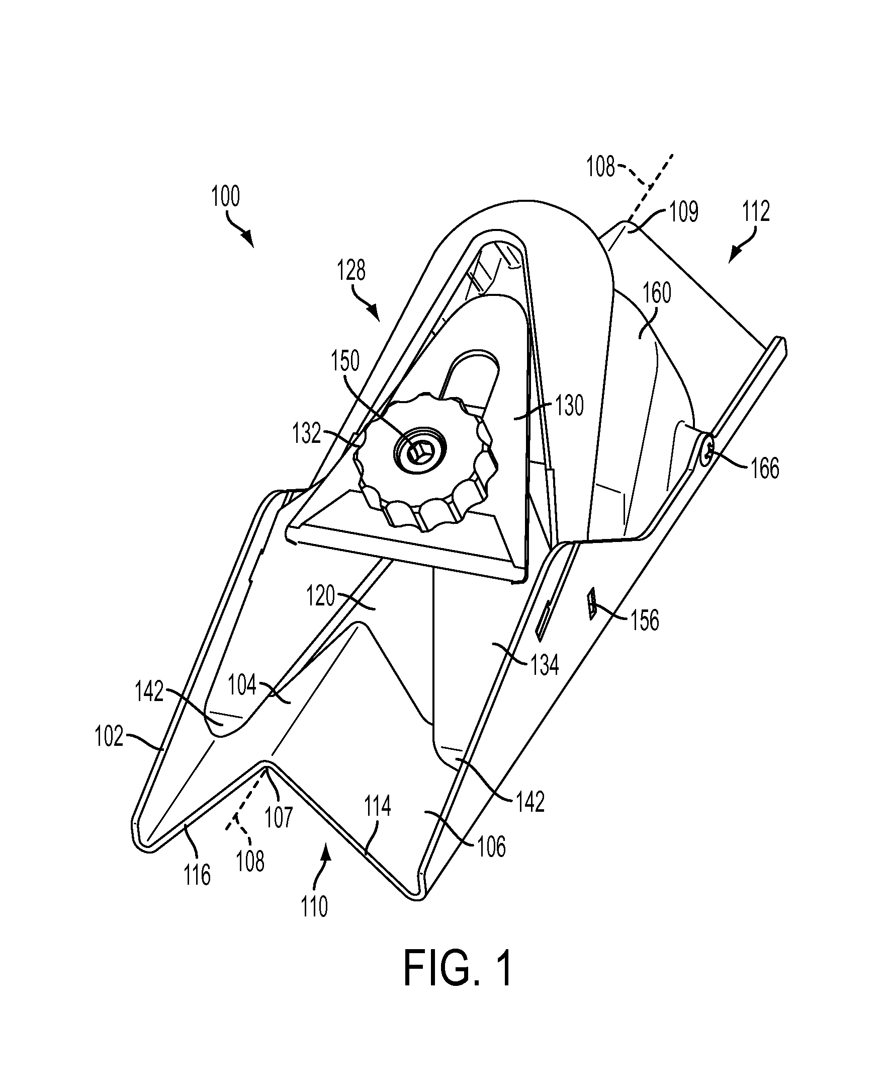
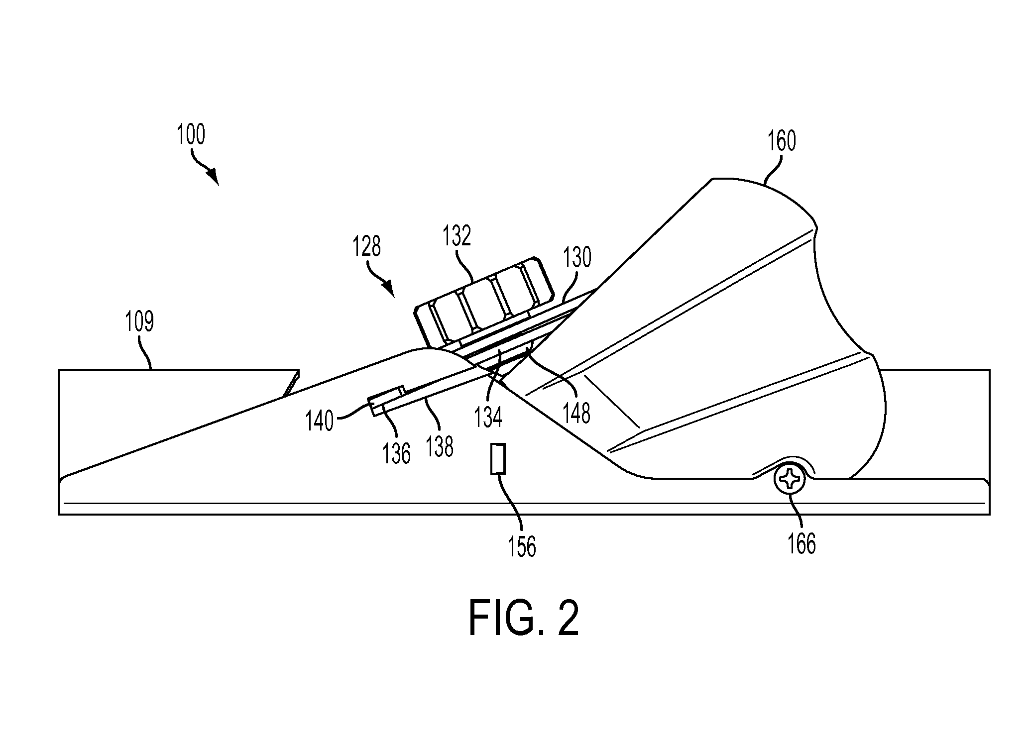
[0027]FIG. 1 shows a perspective view of a chamfering tool 100. The chamfering tool 100 comprises a base 102. The base 102 is generally elongate extending along a longitudinal axis 108. The base 102 has a first wall 104 and a second wall 106 which meet at and extend along the longitudinal axis 108.

[0028]In some embodiments the first and second walls 104, 106 are substantially perpendicular to each other. This means the first and second walls 104, 106 can engage a flat surface and an edge of a work piece which are perpendicular to each other. In other embodiments the angle between the first and second walls 104, 106 can be any suitable angle.

[0029]Typically the work piece is a panel P (see FIG. 7) such as a portion of drywall. Hereinafter the work piece will be referred to as a panel P although other objects with elongate edges could be used with the chamfering tool. The panel P comprises large flat surfaces and a thin edge.

[0030]The base 102 of the chamfering tool 100 comprises a bo...


PUM


Abstract

A chamfering tool comprising: a base having first and second walls meeting each other along a longitudinal axis and defining a longitudinal recess along the bottom of the base for engaging a work piece and a longitudinal ridge along the top of the base; a viewing window in the base for viewing the work piece, the viewing window intersecting the longitudinal recess and the longitudinal ridge; and a blade clamp mounted on the base and arranged to clamp at least part of a blade in the viewing window.

Description

FIELD OF THE INVENTION[0001]The present invention relates to a chamfering tool.BACKGROUND OF THE INVENTION[0002]With the current population growth in the world today there is great importance on constructing new buildings for a variety of purposes. New construction techniques often require efficient processes for a quicker build time. One such technique is to use drywall (also known as plasterboard) panels in the interior fitting of the building. The drywall panel provides a premade surface for the interior of the building which can be decorated with minimal treatment beforehand. One such use of drywall panels is in the interior layout of the building whereby interior walls are constructed from a lightweight timber frame and the drywall panels are fixed to the timer frame.[0003]Drywall is manufactured in large rectangular panels but often the drywall must be worked and shaped before use. For example if two pieces of drywall are required to meet at a corner, a 45 degree chamfer can b...

Claims


Application Information

Patent Timeline
IPC IPC(8): B26B29/06B28D1/30
CPCB28D1/30B26B29/06B27D5/006B27G17/025
Inventor CHERNYSHOU, ALIAKSEI
Owner STANLEY WORKS THE
Why Eureka
Try Eureka