Multifunction foot pedal
Active Publication Date: 2015-02-19
JOHNSON & JOHNSON SURGICAL VISION INC
0 Cites 24 Cited by
AI-Extracted Technical Summary
Problems solved by technology
However, electro-mechanical switches introduce a variety of issues.
For example, a foot pedals incorporating a plurality of physical switches can complicate the design of the foot pedal, increase its cost, and increase the potential for failure of a switch.
Further, the placement of the switches may be less than optimal for a particular user, and cannot be modified or adapted to accommodate the user.
This can decrease their e...
Method used
[0047]FIG. 2 is an illustration of an exemplary foot pedal such as foot pedal 104. FIG. 2 shows treadle 201 and switches 202 and 203, although other switch and treadle configurations may be used. For example, switches may be placed on other parts of the foot pedal, or may be located apart from the pedal and coupled thereto, or may be entirely eliminated. An advantage of avoiding or minimizing the use of switches on the foot pedal is to avoid or minimize the number of components that may become fouled during ordinary use, and that may malfunction or fail as a result.
[0048]As illustrated in FIG. 3, in an embodiment, the pitch range of motion of a foot pedal treadle may be divided into four zones, FP0, FP1, FP2, and FP3, corresponding to four virtual switches SW0, SW1, SW2, and SW3, respectively, with a dead-band 301, 302 at each end of the foot pedal travel range of pitch movement. The treadle settles at default position 303 when it is fully released. Although default position 303 is shown as being in the middle of dead-band 301, other default positions may be implemented. In an embodiment, the default pitch position may be configurable. The number of switch zones may also be configurable. Implementing more switch zones would give the user more options for control, while fewer switch zones would give the user more foot pedal travel between switch zones and easier control of the pedal's position. Similarly, as illustrated in FIG. 4, in an embodiment the yaw range of motion of a foot pedal treadle may be divided into four zones, YP0, YP1, YP2, and YP3, corresponding to four virtual switches SW0, SW1, SW2, and SW3, respectively, with a dead-band 402, 403 at each end of the foot pedal travel range. When released, the treadle settles at default position 401, which is shown in the center of the yaw range of motion, although other default positions may be implemented. As before, the default position, and/or the number of switch zones, may be configurable.
[0058]The three traditional positions (“position” as used herein shall mean the disposition of a foot pedal treadle in a zone defined by a particular range of motion for a particular setting, e.g. irrigation) of the treadle in phaco...
Benefits of technology
[0014]Other features and advantages of the disclosed surgical control devices and methods should be apparent from the...
Abstract
A foot pedal with a treadle that pivots up and down to vary its pitch, and/or side to side to vary its yaw. The pivot range of motion is divided into a plurality of zones, each zone configured to correspond to a respective virtual switch. When the treadle is pivoted into one of the zones, the corresponding virtual switch is activated. The virtual switch controls an operatively coupled device such as a handpiece used in a surgical procedure.
Application Domain
Controlling membersMechanical apparatus +5
Technology Topic
Range of motionEngineering +3
Image
Examples
- Experimental program(1)
Example
[0024]The following description and the drawings illustrate specific embodiments sufficiently to enable those skilled in the art to practice the described system and method. Other embodiments may incorporate structural, logical, process and other changes. Examples merely typify possible variations. Individual components and functions are generally optional unless explicitly required, and the sequence of operations may vary. Portions and features of some embodiments may be included in or substituted for those of others.
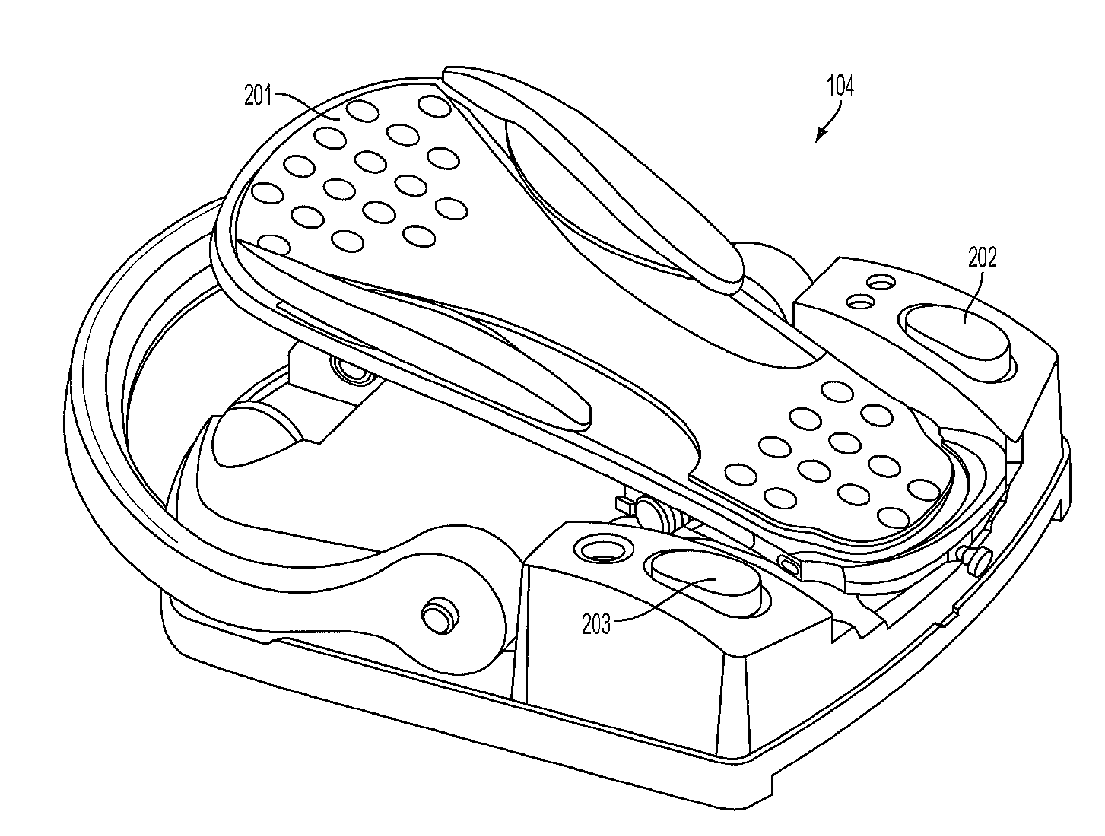
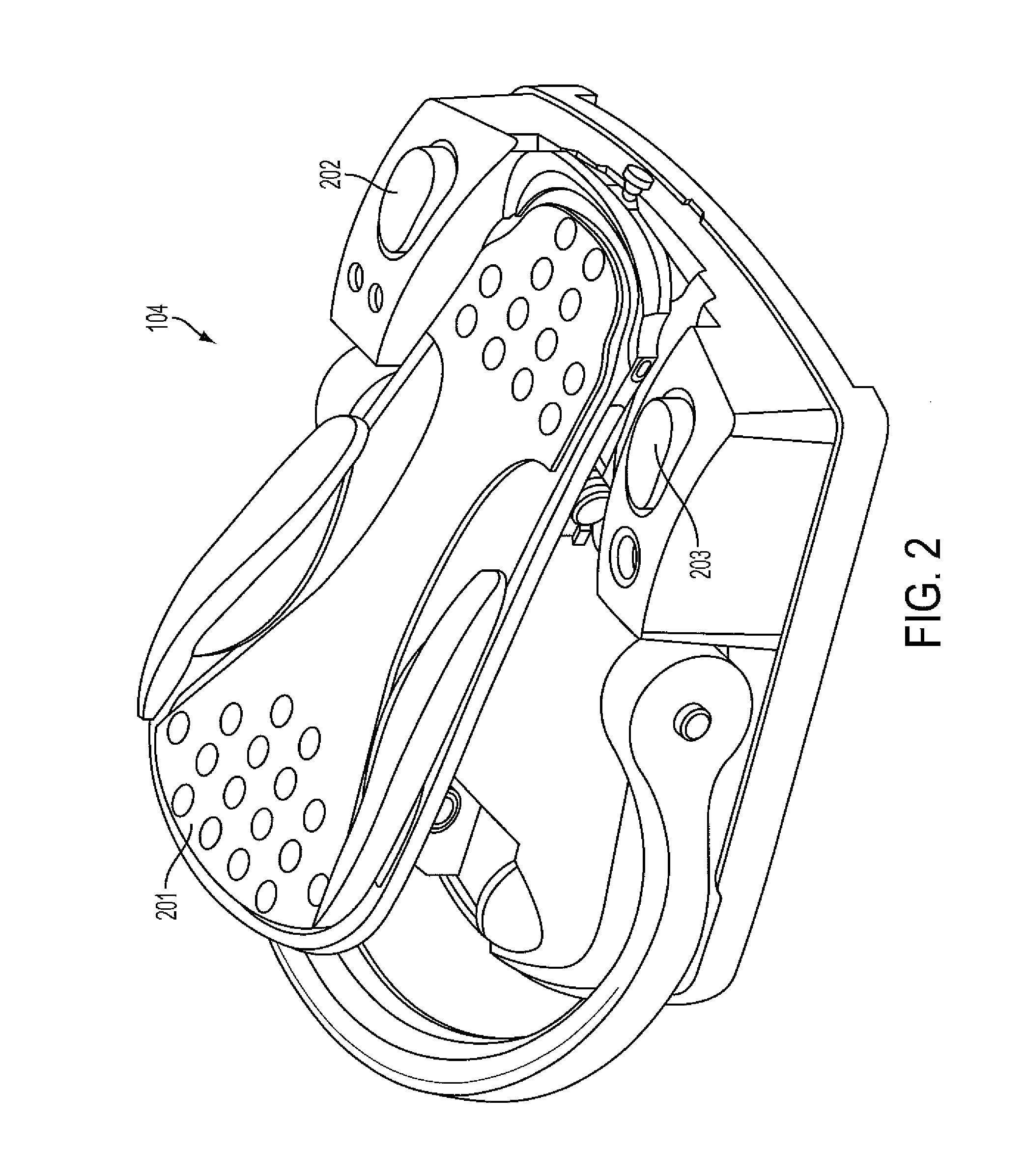
[0025]In an embodiment, the functionality provided by electromechanical switches is produced instead by using the pitch of the foot pedal treadle in the vertical direction, or the yaw of the foot pedal treadle in the horizontal direction, or both. Such an embodiment allows for, but does not require, the elimination of the electromechanical switches and the simplification of the foot pedal hardware design. In an embodiment, a feedback signal may be provided to the user indicating the state of the pedal has been changed, such as an audible signal, a vibration signal, a visual signal such as a flashing light or an indicator on the GUI, or combinations of these.
[0026]A plurality of different conditions of the treadle may be used to define state changes in the foot pedal. Such conditions may include, for example, a pivotably movable treadle that can pivot in a vertical direction about a horizontal axis, called pitch, or in a horizontal direction about a vertical axis, called yaw, or both. In either case, the angle of pitch and/or yaw may be recognized as defined states or as points of transition from one state to another. The maximums of the ranges of motion may also be recognized, such as the top and/or bottom of the pedal's pitch, or the maximum left and/or right yaw. In addition, a particular speed and extent of motion, such as a tap or stomp of the pedal, may be recognized. Furthermore, a duration of maintaining a pedal position may also be recognized, such as pressing a pedal for a couple of seconds and releasing it to turn a feature on or off. Such foot pedal states and/or state changes may be used to define a plurality of virtual switches. That is, the operation of a plurality of physical switches may be mimicked by a corresponding plurality of states or state changes of a single foot pedal treadle. The states or state changes of the treadle are used to define a plurality of virtual switches.
[0027]In embodiments, the pitch, or angle of incline, of the treadle from a reference position such as horizontal, and/or the yaw of the treadle from a reference position such as a center of a range of horizontal movement, can be used to define a plurality of zones. For example, a plurality of zones may be defined, each zone existing between two different angles of pitch or yaw. Such zones may be defined to be active or passive. For example, a plurality of active zones may be configured to be adjacent to each other, or alternatively two active zones may be separated by an inactive zone.
[0028]In embodiments, virtual switches can be used in conjunction with one or more physical switches. For example, one of a plurality of physical switches on or coupled to a foot pedal with a movable treadle may be used to turn on or off the virtual switch functionality of a foot pedal having predefined virtual switches.
[0029]In an alternative embodiment, a foot pedal tap may enter the mode where the user can control virtual switches based upon pitch or yaw. Once the foot pedal is in the “virtual switch on” mode, moving the foot pedal to a predefined state, such as into one of a plurality of defined foot pedal zones, may activate the corresponding virtual switch. The activation may be confirmed by a visual, audible, or haptic signal to provide feedback to the user.
[0030]In an embodiment, the pitch range of motion of a foot pedal treadle may be divided into four zones, with a dead-band at the top and bottom of the foot pedal travel range. When released, the treadle settles at a default position, such as toward the top of the range, when it is fully released. In another embodiment, the yaw range of motion of a foot pedal treadle may also be divided into four zones, with a dead-band at the left and right ends of the foot pedal travel range. When released, the treadle will settle at default position, such as the center of the range.
[0031]In embodiments, there are two primary types of system control functions. One of these is the toggling of discrete functions, such as turning on and off a continuous flow of irrigation fluid. The other primary type includes press-and-hold functions, such as raising and lowering an IV pole to a desired height. Both types of functions can be controlled using virtual switches.
[0032]In an embodiment, to turn a function on and off in toggle mode, the user may press the pedal treadle to a selected switch zone, and then quickly release the pedal. For example, if foot pedal pitch zone 1 is defined as controlling irrigation fluid, the user may move the treadle into pitch zone 1 and quickly release it. The first such movement may turn irrigation on, and a second such movement may turn irrigation off.
[0033]In an embodiment, to turn a function on and off in press-and-hold mode, such as adjusting the height of the IV pole, mode activation occurs when the user holds the treadle in a specific switch zone for at least a defined amount of time, for example, for at least two seconds. The switch zone will then remain active until the user moves the pedal out of that specific switch zone.
[0034]In an embodiment, to exit a virtual switch on pitch mode, the user may press the foot pedal treadle all the way down to its full travel position and hold it there for a predetermined duration, for example, for two seconds. Thereby, the mode is ended, which may be confirmed by one or more of an audible or haptic signal to the user or a visual indicator on the GUI. The user can then return the foot pedal to its default “zero” position to return to normal, non-virtual switch foot pedal operation. In an embodiment, the predetermined duration may be configurable.
[0035]Similarly, to exit a virtual switch on yaw mode, the user may push the foot pedal treadle all the way to its right or left to the full extent of travel and hold for a predetermined, and possibly configurable, duration. Thereby, the mode is ended, which may be confirmed by one or more of an audible or haptic signal to the user or a visual indicator on the GUI. The user can then return the foot pedal to its default “zero” position to return to normal, non-virtual switch foot pedal operation.
[0036]In an embodiment, the previously described exit from virtual switch on pitch or yaw procedure can act as a means for canceling or exiting from a switch activation procedure, without completing any switch activations.
[0037]In an embodiment, the tap to enter the virtual switch on pitch mode may be defined as a quick transition from a first to a second pedal position, and back to the first. For example the foot pedal range of motion may be partitioned into four different zones FP0, FP1, FP2, and FP3, corresponding to virtual switches SW0, SW1, SW2 and SW3. Each switch may be configured for a specific function, or may also be disabled, for example via configuration software running on GUI host 101 or instrument host 102. Though these switch positions may correspond to the standard foot pedal positions FP0, FP1, FP2, and FP3, the switch zones could be configured independently as well. For example, the pedal may be programmed to have functionality that does not correspond to the standard foot pedal positions, and/or may be programmed with more or fewer pitch zones.
[0038]In an exemplary illustration, the switches are configured as SW0=IV Pole Down, SW1=IV Pole Up, SW2=Previous Major Mode, and SW3=Next Major Mode; and the user is a surgeon. In an exemplary operation, the surgeon enters the virtual switch on pitch mode by pressing the foot pedal into the SW0 zone for a predetermined duration. This action causes the pedal to enter the switch on pitch mode, which is confirmed by an audible or haptic feedback and display on the GUI. Upon staying in the SW0 zone for the predetermined time, an IV Pole Down command is sent to the IV pole and it starts lowering. Any transition out of the SW0 zone results in an IV Pole Stop command being sent to the IV pole, halting its downward motion. Had the surgeon held the pedal in the SW1 zone instead of the SW0 zone, the surgeon would have received distinctive feedback sufficient to identify the zone as SW1, such as 2 distinct audible or vibration feedback signals for example. Upon holding the pedal in the SW1 position for the predetermined duration, an IV Pole Up command is sent to the IV pole and it starts rising. Any transition out of the SW1 zone results in an IV Pole Stop command being sent to the IV pole, halting its upward motion.
[0039]If the surgeon proceeds into the SW2 zone and quickly releases to the FP0 position, this is interpreted by the instrument host 102 as activation of virtual switch SW2. Since SW2 is configured as Previous Major Mode in this illustration, the system would transition backward to the previous major mode available in the system. Similarly, moving the pedal into the SW3 zone would result in proceeding to the next major mode available in the system. At any time during operation of the pedal in the switch on pitch mode, pressing and holding the foot pedal treadle at full travel for a predetermined time results in exiting the switch on pitch mode, and returning to standard pedal operation.
[0040]Similarly, in a switch on yaw mode illustrative example, the foot pedal may be partitioned in switch zones that are laid out from left to right. For this example SW0 and SW1 are defined to be to the right of a center default pedal position or dead-band, and SW2 and SW3 to the right. The functionality of the virtual switch on yaw example operates similarly with regard to the switch behavior. One difference is the zero may be the center dead-band reference instead of toward a limit of motion. From the switch on yaw mode of operation, holding the pedal for a predetermined duration in one of the dead-bands at the left and right limit of the yaw travel range would exit the switch on yaw mode.
[0041]Other embodiments combine switching on pitch and/or yaw modes with any desired number of electro-mechanical switches. Any convenient number and location of electro mechanical switches may be implemented on or with a pedal or other controller that provides virtual switches based on the position of a control element. Combining electro mechanical switches with the virtual switch on pitch or yaw functionality offers a great number of possibilities.
[0042]Although the primary exemplary embodiments use a foot pedal pitch or yaw, analogous embodiments may be implemented using any control, such as a twist knob or lever, which provides angular data for control purposes. Any type of lever, twist dial, foot pedal, or the like used in any industry or other control context may benefit from this approach. Such controls might be a throttle lever on a vehicle, or a twist knob on an instrument control panel, or a foot pedal used with a musical instrument or a sewing machine, for example.
[0043]Embodiments of foot pedal control systems and methods will be discussed herein with a particular emphasis on a medical or hospital environment in which an ocular surgeon practices. For example, an embodiment may be part of a phacoemulsification surgical system that comprises an integrated high-speed control module for a handpiece. The surgeon may set or adjust a vibration speed via the GUI or foot pedal to control a phacoemulsification handpiece.
[0044]Referring now to FIG. 1, a block diagram is shown illustrating an exemplary phacoemulsification system 100. In the exemplary system, GUI host 101 and instrument host 102 may be distinct components communicatively coupled, or may reside on a single-board computer and communicate through inter-process communication. Such components or computer comprise hardware, including at least a microprocessor and at least one data storage device, such as a hard drive or flash memory, random access memory (RAM), or the like. Instrument host 102 typically takes the form of a computational device in the arrangement shown, but other arrangements are possible. For example, an interface of instrument host 102 may be communicatively coupled to other locations, systems, subsystems, and modules within and/or external to the instrument host 102, for distribution of instrument sensor data, instrument settings, parameter information, and the like.
[0045]Foot pedal 104 is communicatively coupled through a wired or wireless communications port to instrument host 102, and transmits control signals relating to the foot pedal treadle's physical position, corresponding virtual switch position information, or both, to the instrument host. Instrument host 102 may store in its storage device a database of configuration parameter values, executable programs, other data, and the like. In the exemplary embodiment, the treadle position or corresponding virtual switch position information can be converted by the instrument host 102 into a programmed switch function which is controlled by modifying the incline and/or orientation of the treadle by the user, as will be described.
[0046]In the exemplary system, a phacoemulsification handpiece 110 includes a needle, and means for ultrasonically vibrating the needle such as a piezoelectric crystal. The instrument host 102 provides power via electrical connection 111 to handpiece 110. An irrigation fluid (IF) source 112 can be coupled via a tube or other fluid channel 113 to the handpiece to provide irrigation fluid to handpiece 110. The irrigation fluid and ultrasonic power are applied using handpiece 110 to a subject eye (not part of the system) represented by block 103. Aspiration is provided to eye 103 by a pump (not shown), such as a peristaltic pump and/or Venturi pump, via the instrument host 102, through lines 115 and 116. A surgeon/operator may control the operation of the handpiece using control elements disposed on any or all of the handpiece, the instrument host 102, the GUI host 101, and foot pedal 104.
[0047]FIG. 2 is an illustration of an exemplary foot pedal such as foot pedal 104. FIG. 2 shows treadle 201 and switches 202 and 203, although other switch and treadle configurations may be used. For example, switches may be placed on other parts of the foot pedal, or may be located apart from the pedal and coupled thereto, or may be entirely eliminated. An advantage of avoiding or minimizing the use of switches on the foot pedal is to avoid or minimize the number of components that may become fouled during ordinary use, and that may malfunction or fail as a result.
[0048]As illustrated in FIG. 3, in an embodiment, the pitch range of motion of a foot pedal treadle may be divided into four zones, FP0, FP1, FP2, and FP3, corresponding to four virtual switches SW0, SW1, SW2, and SW3, respectively, with a dead-band 301, 302 at each end of the foot pedal travel range of pitch movement. The treadle settles at default position 303 when it is fully released. Although default position 303 is shown as being in the middle of dead-band 301, other default positions may be implemented. In an embodiment, the default pitch position may be configurable. The number of switch zones may also be configurable. Implementing more switch zones would give the user more options for control, while fewer switch zones would give the user more foot pedal travel between switch zones and easier control of the pedal's position. Similarly, as illustrated in FIG. 4, in an embodiment the yaw range of motion of a foot pedal treadle may be divided into four zones, YP0, YP1, YP2, and YP3, corresponding to four virtual switches SW0, SW1, SW2, and SW3, respectively, with a dead-band 402, 403 at each end of the foot pedal travel range. When released, the treadle settles at default position 401, which is shown in the center of the yaw range of motion, although other default positions may be implemented. As before, the default position, and/or the number of switch zones, may be configurable.
[0049]In an embodiment, the yaw directional movement configured to implement one or more virtual toggle switches, and the pitch directional movement configured to implement one or more virtual press-and-hold (“linear”) controls, or vice versa. Partial virtual switch and partial virtual linear controls may be configured for either or both of the yaw directional movement and the pitch directional movement. Virtual linear controls may be configured for both yaw and pitch. Particular virtual switches may be configured for particular features, such as a first virtual switch for a first pump, a second virtual switch for a second pump, and a third virtual switch for irrigation. Any virtual switch may be paired with a linear control, for example using one of the yaw or pitch to select a particular function, and the other of the yaw or pitch to adjust the speed, intensity, or other variable of the particular function. Combinations of these features may also be configured.
[0050]FIG. 5 is a flowchart of an exemplary method of operation of the disclosed foot pedal that implements virtual switches. If one or more of the operational parameters of virtual switches implemented in a foot pedal with rotating treadle are configurable, the method begins at step 505 by configuring those parameters. For example, the various foot pedal position zones, time periods, and the like can be set. If the parameters are not configurable the method begins at step 510, or if they have already been set proceeds to step 510. At step 510, the user enters the virtual switch on mode, which may be confirmed with a feedback signal. Then the user modifies the position of the foot pedal treadle to activate a select virtual switch, 515, which may also be confirmed. For example, the user may adjust the treadle position to be within a select pitch zone, thereby activating the virtual switch that corresponds to that zone and enabling the corresponding function in apparatus that is operably coupled to the foot pedal. Activation of the virtual switch may be confirmed with a visual, audible, and/or haptic signal. A control signal is then provided to the apparatus, 520, which can then be used to perform the enabled function, 525. When complete, the user can modify the position of the treadle to activate a different virtual switch, returning to step 515 and proceeding from there. When the user has finished using the virtual switches, the user may terminate the virtual switch on mode, 530.
[0051]As shown in FIG. 6, in an exemplary embodiment a foot pedal 104 comprises a treadle 501 that moves in a pitch direction. As shown, the range of motion of treadle 501 is divided into three equal zones, A, B, and C. The pedal may be preconfigured to have only these three zones, or may be configurable to have a different number of zones, and/or zones that have configurable ranges. Pressing the pedal into one of the zones operates to select and activate a corresponding virtual switch, as described previously. The activation of a select switch can be confirmed by a feedback signal to the user, such as one or more of an audible, haptic, or visual signal as described previously. FIG. 7 shows the pedal 104, now configured to divide the pitch range of motion of treadle 501 into six zones A, B, C, D, E, and F.
[0052]FIG. 8 shows an exemplary pedal 104 with a treadle 501 able to move in a yaw direction. As shown, the range of motion of treadle 501 is divided into two equal zones, X and Y. The pedal may be preconfigured to have only these two yaw zones, or may be configurable to have a different number of zones, and/or zones that have configurable ranges. Turning the pedal into one of the zones operates to select and activate a corresponding virtual switch, as described previously. The activation of a select switch can be confirmed by a feedback signal to the user, such as one or more of an audible, haptic, or visual signal as described previously. FIG. 9 shows the pedal 104, now configured to divide the pitch range of motion of treadle 501 into three zones X, Y, and Z.
[0053]In an embodiment, a plurality of programmed settings may be saved as a set, such as a set of personal preferences of a particular user, and may be loaded into instrument host 102 to adapt the operation and functionality of the foot pedal to the user. In addition, a user may save different sets of programmed settings to use different surgical techniques, or to meet particular situations encountered during surgery, such as the density of a subject lens, intraoperative exigencies, and different parts of a procedure, such as sectioning, chopping, and/or polishing. In an embodiment, the user may change from a first set of programmed settings to a second set of settings by activating a particular electromechanical or virtual switch of the foot pedal.
[0054]In an embodiment, an ocular surgical apparatus can comprise an apparatus control device, such as a foot pedal communicatively coupled to an instrument host 102, configured to control at least one parameter of the apparatus. The instrument host 102 receives signals from the surgical control device, and evaluates the signals to implement one of a plurality of virtual switches or other virtual control mechanisms.
[0055]Unless otherwise indicated, the order of method steps described in connection with any embodiment may be varied without departing from the scope of the invention. Moreover, the various exemplary logical blocks, modules, circuits, algorithm steps, and the like described in connection with the disclosed embodiments may be implemented as electronic hardware, computer software executing on a computing device that includes at least a processor coupled to a memory device on which the software is stored, or combinations of both. Because of the various possible implementations, various illustrative components, blocks, modules, circuits, and steps may have been described herein generally in terms of their functionality. Whether such functionality is implemented in application specific hardware or in software executing on a general purpose computing device may depend, for example, upon the particular application and physical or cost constraints imposed on the overall system. Although the described functionality may be implemented in various ways for each application, the implementation decisions do not cause a departure from the scope of the present invention as set forth the claims.
[0056]In particular, the various illustrative logical blocks, modules, and circuits described in connection with the embodiments disclosed herein may be implemented or performed using a general purpose processor, a digital signal processor (DSP), an application specific integrated circuit (ASIC), a field programmable gate array (FPGA) or other programmable logic device, discrete gate or transistor logic, discrete hardware components, or any combination thereof designed to perform the functions described herein. A general purpose processor may be a microprocessor, but in the alternative, the processor may be any conventional processor, controller, microcontroller, or state machine. A processor may also be implemented as a combination of computing devices, e.g., a combination of a DSP and a microprocessor, a plurality of microprocessors, one or more microprocessors in conjunction with a DSP core, or any other such configuration.
[0057]The steps of a method or algorithm described in connection with the embodiments disclosed herein may be embodied directly in hardware, in a software module executed by a processor, or in a combination of the two. A software module may reside in RAM memory, flash memory, ROM memory, DOM memory, EPROM memory, EEPROM memory, registers, hard disk, a removable disk, a CD-ROM, or any other form of storage medium known in the art. An exemplary storage medium may be coupled to the processor such that the processor can read information from, and write information to, the storage medium. In the alternative, the storage medium may be integral to the processor. The processor and the storage medium may reside in an application specific integrated circuit (ASIC). The ASIC may reside in a user terminal. In the alternative, the processor and the storage medium may reside as discrete components in a user terminal.
[0058]The three traditional positions (“position” as used herein shall mean the disposition of a foot pedal treadle in a zone defined by a particular range of motion for a particular setting, e.g. irrigation) of the treadle in phacoemulsification include: position 1 for irrigation; position 2 for irrigation and aspiration; and position 3 for irrigation, aspiration, and ultrasonic power. When the foot pedal is in a resting position, there are no pumps running or ultrasonic power being exerted. Position 1 allows for irrigation of fluid to the eye from an irrigation source. The travel of the treadle within the first position may control the flow rate of fluid into the eye. Position 2 activates one or more pumps that are capable of increasing flow of fluid into and through the eye, aspirate fluid and lens material from the eye, and/or venting towards the eye to relieve pressure build up in the medical device system. The travel within position 2 may be programmed to control how the one or more pumps operate. For example, as the user continues to travel farther within a position, the aspiration rate may increase, the pump rate may increase, or the vacuum pressure may increase. Position 3 activates the ultrasound energy, which is used to help emulsify and/or break up the lens material. The travel within position 3 may be programmed to control, inter alia, how much power is exerted on the lens material, how the power is exerted (e.g. burst, pulse, etc.), and the length of time the power is on (duty cycle). With the present invention the user may move the treadle to various locations within the available degree of movement to set where each option begins and ends, as well as the type of control occurring within each beginning and ending, e.g., percent power distribution, type of pulses, vacuum level distribution, etc. The user may also set within a selected range of movement of the treadle how the particular programming setting will perform. For example, the ultrasonic power may increase linearly as the foot pedal is depressed or the power may increase at a set increment until a particular degree of travel of the treadle has been reached and then increments may become smaller or larger depending upon the user's preference.
[0059]For a dual action foot pedal, a user may program a pitch directional movement and/or a yaw directional movement to correspond to one or more settings. In an embodiment, to program a directional movement, a user selects either the pitch or the yaw directional movement of the treadle of the foot pedal by indicating the selection on a display screen, by moving the treadle in the selected directional movement, by activating a switch on the foot pedal itself, by voice command, or combinations thereof. Once the user has made a selection, the display screen will show all of the available programming settings for the selected directional movement. The available programming settings include, but are not limited to, irrigation and rate thereof, aspiration and rate thereof, choice of pump and control thereof, vacuum and control thereof, ultrasonic power and control thereof, and combinations thereof. Additional programming settings include use of a combination of pumps or switching between pumps; controlling the linear relationship between movement (travel of the treadle) and the programming setting; proportional relationship between movement and control of a programming setting (e.g. 5 mm (or 2°)=10 mmHg vs. 10 mm (or 4°)=100 mmHg; or 5 mm (or 2°)=10 Hz vs. 10 mm (or 4°)=100 Hz); and/or panel movement (constant rate within a particular zone or degree of movement of the treadle) of the programming settings. By pitching the foot pedal up and down, or yawing the foot pedal to the left and/or right, the user can modify the foot pedal and its degree of depression or yaw to correspond to a particular program setting. During configuration of the pedal, when a first designated position is reached, the user may indicate (confirm) the choice on the display screen or write in (save setting(s) in memory) the particular setting by any other mechanism described herein or known in the art, such as voice command and/or tap switch, and continue moving the foot pedal to a second designated location. When the second designated location is reached, the user may confirm the choice as a second setting. The user may continue until all of the desired and/or allowed settings for the directional movement of the foot pedal are set. When the dual linear foot pedal is used as described herein, it allows a user to control the functions, modes, and/or settings, simultaneously by using pitch, yaw, and combinations thereof. The interface may provide feedback to the user to confirm the settings for the pitch and/or yaw direction of the treadle.
[0060]Other mechanisms for setting and/or programming a particular setting may be employed including, but not limited to, clicking on an icon on a display screen using a mouse or touch screen, depressing a button or physical switch on a foot pedal, voice activated commands and/or combinations thereof.
[0061]The term “phacoemulsification” refers to a method of lens and cataract extraction from an eye. The procedure includes an ultrasonically vibrated needle which is inserted through a very small incision in the cornea in order to provide energy for emulsifying or breaking up of the lens and cataract which then can be aspirated and removed through the incision.
[0062]The term “diathermy” refers to a method of cautery to seal severed or ruptured blood vessels. Diathermy is used in ophthalmic surgery to halt bleeding associated with surgical incisions.
[0063]The term “vitrectomy surgery” refers to a method employed during cataract surgery when the posterior capsular bag has been broken and in the treatment of retinal detachments resulting from tears or holes in the retina. In cataract surgery, the same incision used for the phacoemulsification handpiece is used for inserting the vitrector to remove the vitreous gel. Vitrectomy surgery typically involves removal of vitreous gel and may utilize three small incisions in the pars plana of the patient's eye. These incisions allow the surgeon to pass three separate instruments into the patient's eye to affect the ocular procedure. The surgical instruments typically include a vitreous cutting device, an illumination source, and an infusion port.
[0064]The term “display” or “display screen” as used herein shall mean a graphical user interface (GUI), a screen, a monitor, touch screen, or any other device known in the art for displaying a visual picture or representation.
[0065]The previous description is provided to enable a person of ordinary skill in the pertinent arts to make or use the invention. Various modifications to the disclosed embodiments will be readily apparent to those skilled in the art, and the generic principles defined herein may be applied to other embodiments without departing from the spirit or scope of the invention. Thus, the present disclosure is not intended to be limited to the embodiments shown herein but is to be accorded the widest scope consistent with the principles and novel features disclosed herein.
[0066]According to an embodiment, upon attachment of a foot pedal to a medical device system, the interface of the system will recognize the type of foot pedal and the features of the foot pedal. A foot pedal may be attached to the medical device system by any mechanism known in the art, including, but not limited to, a wire connection and a wireless connection, e.g. Bluetooth® or IR. A display screen of the medical device system may present the user with a picture or representation of the foot pedal detected. The picture or representation may show all the switches and directional movements available for programming the attached foot pedal.
PUM


Description & Claims & Application Information
We can also present the details of the Description, Claims and Application information to help users get a comprehensive understanding of the technical details of the patent, such as background art, summary of invention, brief description of drawings, description of embodiments, and other original content. On the other hand, users can also determine the specific scope of protection of the technology through the list of claims; as well as understand the changes in the life cycle of the technology with the presentation of the patent timeline. Login to view more.