Method and apparatus for restoring mechanical relay from stuck fault to normal condition

a technology of mechanical relay and fixed fault, which is applied in contact testing/inspection, electric/fluid circuit, vehicle components, etc., can solve problems such as the failure rate of the ecu, the temporary stuck state may be a failure, and the mechanical relay may be subject to a temporary stuck faul

Active Publication Date: 2015-02-26
HL MANDO CORP
View PDF2 Cites 7 Cited by
  • Summary
  • Abstract
  • Description
  • Claims
  • Application Information

AI Technical Summary

Benefits of technology

[0009]An object of the present invention is to provide a method and apparatus for restoring a mechanical relay from a stuck fault to a normal condition, wherein if a temporary stuck fault attributable to impurities at the contact point of the mechanical relay or a low temperature is generated in the mechanical relay when an Electronic Control Unit (ECU) detects a failure that may affect a driver, an operation of periodically applying an electric current to the coil of the mechanical relay configured to stop a random operation of an actuator by blocking the supply of an electric current to the actuator is repeated so that heat and an electrical movement are provided, thereby being capable of restoring the mechanical relay from the temporary stuck fault to a normal condition and preventing the ECU from being detected as being a failure.

Problems solved by technology

The mechanical relay may be subject to a temporary stuck fault attributable to the impurities of a contact point or a low temperature.
If the mechanical relay is temporarily stuck, the ECU determines such a temporary stuck state to be a failure because the operation of the mechanical relay is unable to be guaranteed.
Accordingly, there is a problem in that the failure rate of the ECU may rise depending on a low temperature condition and the lifespan of the mechanical relay because the ECU determines a temporary stuck fault to be a failure when the temporary stuck fault is generated in the mechanical relay due to the impurities of a contact point or a low temperature.

Method used


Image

  • Method and apparatus for restoring mechanical relay from stuck fault to normal condition
  • Method and apparatus for restoring mechanical relay from stuck fault to normal condition
  • Method and apparatus for restoring mechanical relay from stuck fault to normal condition

Examples


Embodiment Construction

[0022]The present invention may be modified in various ways and may be implemented to have several embodiments. Specific embodiments of the present invention are illustrated in the drawings and are described in detail in the detailed description. It is however to be noted that the present invention is not intended to be limited to the specific embodiments, but is intended to include all modifications, equivalents, or substitutions which fall within the spirit and technical scope of the present invention.

[0023]Embodiments of a method and apparatus for restoring a mechanical relay from a stuck fault to a normal condition according to the present invention are described in detail with reference to the accompanying drawings. In describing the embodiments with reference to the accompanying drawings, the same or corresponding elements are assigned the same reference numerals, and a redundant description thereof is omitted

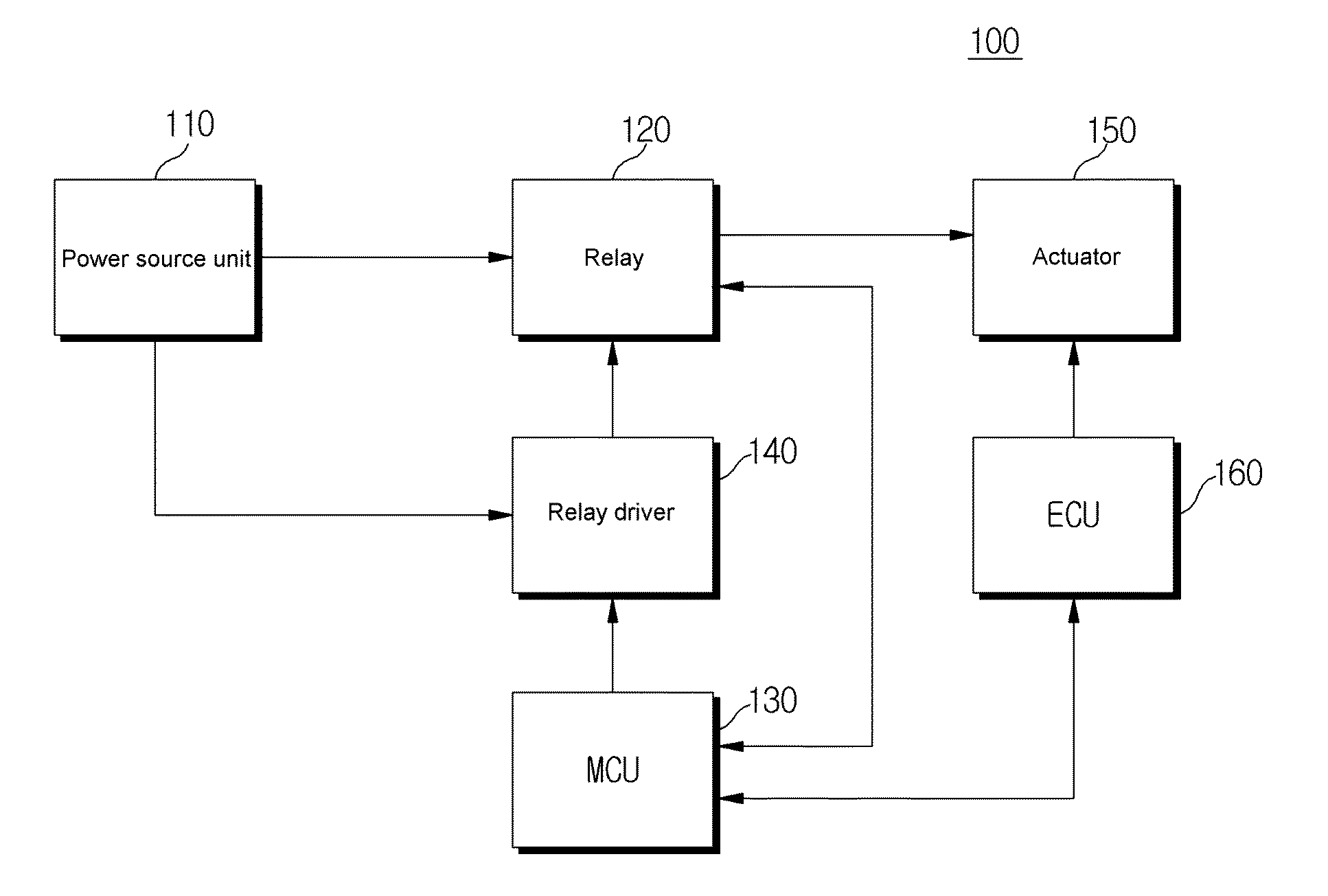
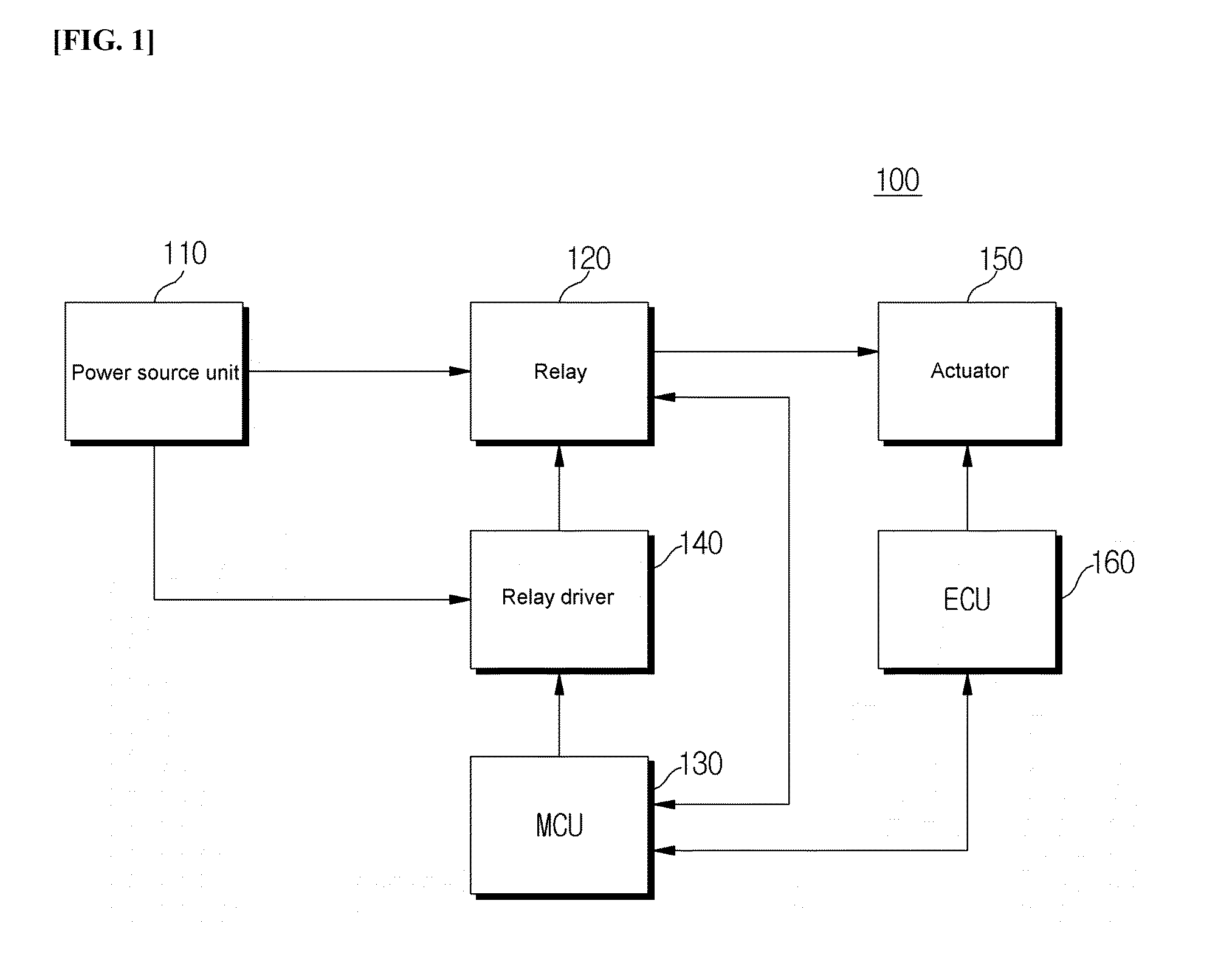
[0024]FIG. 1 is a diagram illustrating the configuration of an appar...


PUM


Abstract

Disclosed herein are a method and apparatus for restoring a mechanical relay from a stuck fault to a normal condition. The method may include detecting, by an MCU, a short state or open state of a relay, repeatedly transferring, by the MCU, a current application signal and a current non-application signal to a relay driver when the relay is in the short state, repeating, by the relay driver, an operation of periodically applying an electric current from a power source unit to the relay in response to the current application signal and the current non-application signal so that the release of the contact point of the relay is induced, detecting, by the MCU, the release state of the contact point of the relay, and maintaining, by the MCU, an ECU in an operating state when the contact point of the relay is released.

Description

BACKGROUND OF THE INVENTION[0001]1. Field of the Invention[0002]Exemplary embodiments of the present invention relate to an apparatus and method for restoring a mechanical relay used in a vehicle from a temporary stuck fault to a normal condition, and more particularly, to a method and apparatus for restoring a mechanical relay from a stuck fault to a normal condition, wherein if a temporary stuck fault attributable to impurities at the contact point of the mechanical relay or a low temperature is generated in the mechanical relay when an Electronic Control Unit (ECU) detects a failure that may affect a driver, an operation of periodically applying an electric current to the coil of the mechanical relay configured to stop a random operation of an actuator by blocking the supply of an electric current to the actuator is repeated so that heat and an electrical movement are provided, thereby being capable of restoring the mechanical relay from the temporary stuck fault to a normal cond...

Claims


Application Information

Patent Timeline
Patent Type & Authority Applications(United States)
IPC IPC(8): H01H47/22
CPCH01H2047/003H01H47/22H01H47/002B60R16/02B60R16/023B60W50/02B60W50/04H01H1/0015H01H3/001
Inventor KIM, DO YOUNG
Owner HL MANDO CORP
Why Eureka
Try Eureka