
Failure detection device for particulate matter filter and method of detecting failure of particulate matter filter

a technology of failure detection and filter, which is applied in the direction of mechanical equipment, machines/engines, instruments, etc., can solve the problems of large sensor output signal fluctuation, large detection error, and difficulty in accurately detecting the occurrence of pm filter failure, so as to reduce the variation of sensor output values, reduce detection errors, and improve detection accuracy

Active Publication Date: 2020-11-24
DENSO CORP
View PDF28 Cites 0 Cited by
  • Summary
  • Abstract
  • Description
  • Claims
  • Application Information

AI Technical Summary

Benefits of technology

[0015]It is therefore desired to provide a failure detection device and a failure detection method of quickly detecting occurrence of a particulate matter filter failure on the basis of a sensor output of a particulate matter detection sensor with high accuracy regardless of a detection type of the particulate matter detection sensor.
[0021]Further, the failure detection method uses the failure detection device having the structure previously described, and sequentially performs the judgment execution determination step and the failure detection step. This makes it possible to perform the failure detection of the particulate matter filter at a correct timing with high accuracy, and reduces a detection error and reduces the variation of the sensor output values transmitted from the particulate matter detection sensor
[0022]As previously described, the present invention provides a failure detection device and failure detection method capable of quickly detecting occurrence of the particulate matter filter failure with high accuracy on the basis of the sensor output signals of the particulate matter detection sensor regardless of the type of the particulate matter detection sensor.

Problems solved by technology

Under this driving state of the own vehicle, it becomes difficult to correctly detect the occurrence of the PM filter failure when a shortened value is used as the predetermined period of time to reach the threshold value at which the process of detecting the PM filter failure is started.
Because the failure detection process of detecting the PM filter failure is intermittently performed, it becomes often difficult to quickly detect failure of the PM filter.
Accordingly, the latter case generates a large fluctuation of the sensor output signal and a large detection error.
This reduces the accuracy of detecting the PM filter failure.
Further, the failure judgment part detects occurrence of a particulate matter filter failure on the basis of the second comparison result.

Method used


Image

  • Failure detection device for particulate matter filter and method of detecting failure of particulate matter filter
  • Failure detection device for particulate matter filter and method of detecting failure of particulate matter filter
  • Failure detection device for particulate matter filter and method of detecting failure of particulate matter filter

Examples


first exemplary embodiment

[0045]A description will be given of a failure detection device for a particulate matter filter (hereinafter, the PM filter) according to the first exemplary embodiment with reference to FIG. 1 to FIG. 9.

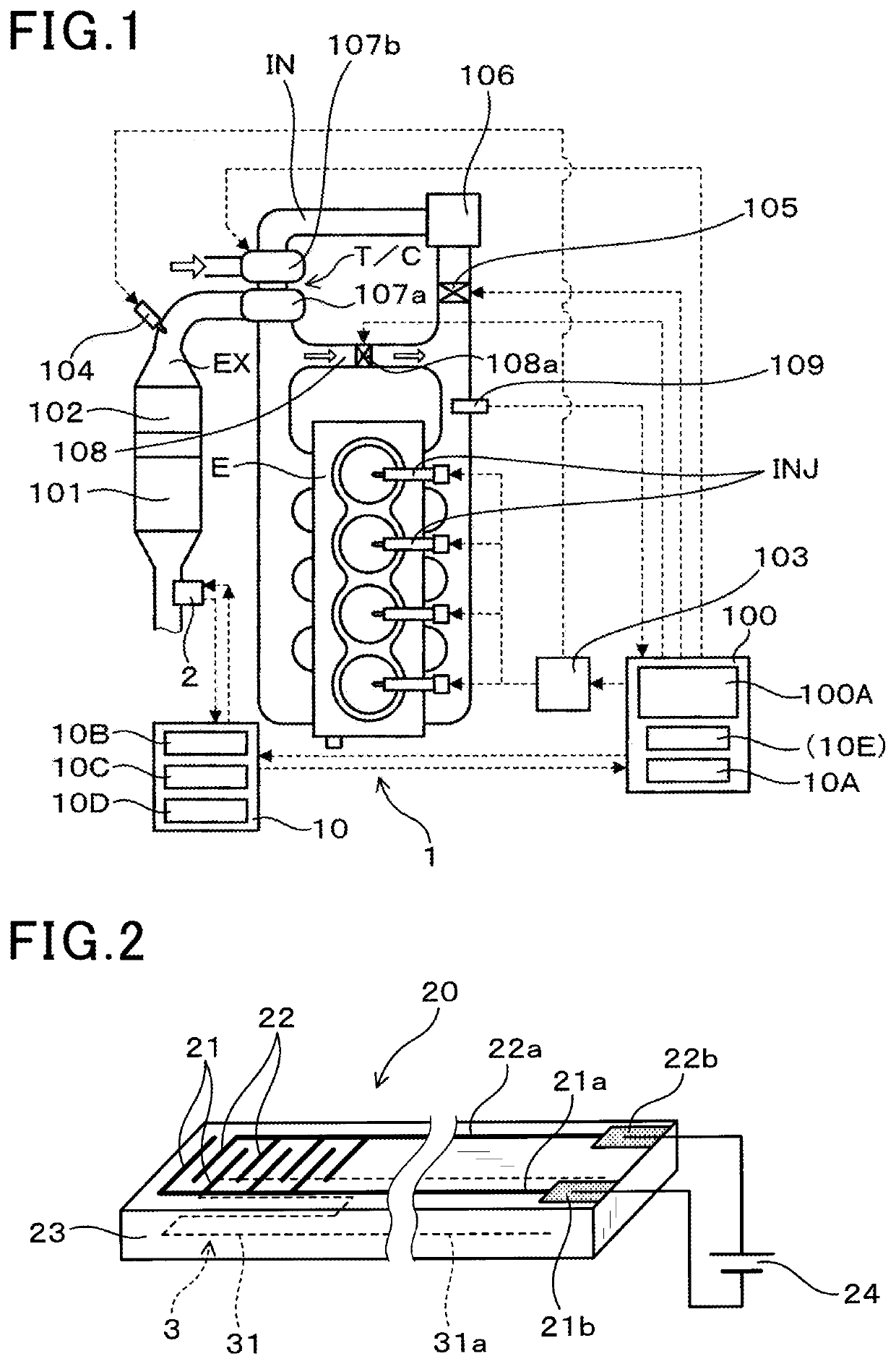
[0046]FIG. 1 is a view showing a schematic structure of an internal combustion engine E (hereinafter, the engine E) equipped with the failure detection device 1 for the PM filter 101 according to the first exemplary embodiment. As shown in FIG. 1, the engine E is a four cylinder direct injection diesel engine having a turbocharger T / C mounted on a vehicle, for example. The PM filter 101 is mounted in an exhaust gas pipe EX as an exhaust gas passage connected to the engine E, through which exhaust gas emitted from the engine E is discharged to the outside of the engine E.

[0047]The failure detection device 1 is mounted on the exhaust gas pipe EX to detect occurrence of failure of the PM filter 101. An oxygen catalyst part 102 is arranged at the upstream side of the PM filter 101 in th...

second exemplary embodiment

[0142]A description will be given of the failure detection process performed by the failure detection device 1 having the PM detection sensor 2 equipped with the sensor part 200 with reference to FIG. 13, FIG. 14A and FIG. 14B, and FIG. 15A and FIG. 15B.

[0143]The same components between the second exemplary embodiment and the first exemplary embodiment will be referred with the same reference numbers and characters. The explanation of the same components is omitted here for brevity.

[0144]As previously shown in FIG. 9, it is known that the actual amount of particulate matter contained in exhaust gas is easily different from the sensor output value S of the PM detection part such as the sensor element 20 in the PM detection sensor 2 when the amount of exhaust gas flowing in the exhaust gas pipe EX is not less than a predetermined amount under a condition in which the own vehicle is running under a large variation state of the engine load. In this case, there is a possible case in whic...

third exemplary embodiment

[0185]A description will be given of the failure detection device 1 according to the third exemplary embodiment with reference to FIG. 16 to FIG. 18.

[0186]FIG. 16 is a view showing a flow chart of the failure detection process of the PM filter 101 performed by the failure detection device 1 according to the third exemplary embodiment of the present invention. The same components between the third exemplary embodiment and the second exemplary embodiment will be referred with the same reference numbers and characters. The explanation of the same components is omitted here for brevity.

[0187]When the PM detection sensor control part 10 decides whether the failure detection process should be performed on the basis of the continuous period in which the engine E has the predetermined load L, there is a possible case in which it may be difficult to perform the failure detection process adequate number of times when a large variation of the load L of the engine E is continued, as shown in FI...


PUM

PropertyMeasurementUnit
execution threshold value L0aaaaaaaaaa
temperatureaaaaaaaaaa

Abstract

A failure detection device has a PM filter, a PM detection sensor having a sensor element arranged at a downstream of the PM filter, an ECU and a PM detection sensor control part. The sensor element detects an amount of PM in exhaust gas, and generates a sensor signal corresponding to the detected PM amount. A load detection part in the ECU detects an engine load. A judgment execution determination part in the control part compares the detected engine load with a threshold value, and determines whether a PM filter failure detection should be performed based on the comparison result. A failure judgment part compares the sensor signal with a failure judgment threshold value when the determination part decides that it is necessary to perform the failure detection of the PM filter, and determines that the PM filter failure has occurred based on the latter comparison result.

Description

CROSS-REFERENCE TO RELATED APPLICATION[0001]This application is related to and claims priority from Japanese Patent Application No. 2017-138425 filed on Jul. 14, 2017, the contents of which are hereby incorporated by reference.BACKGROUND OF THE INVENTION1. Field of the Invention[0002]The present invention relates to failure detection devices and methods of detecting a failure of a particulate matter filter which is capable of collecting particulate matter contained in exhaust gas emitted from an internal combustion engine.2. Description of the Related Art[0003]Recently, in view of environmental consciousness, pollution control standards and regulations on chemicals, particulate matter, or biological materials contained in exhaust gas emitted from an internal combustion engine for manufacturing plants, factories, various types of vehicles, etc. are becoming stricter year by year. Accordingly, there is a strong demand to provide a particulate matter filter (a PM filter) and a particul...

Claims


Application Information

Patent Timeline
Patent Type & Authority Patents(United States)
IPC IPC(8): G01N15/06G01N15/08F01N11/00F01N3/021G01N15/00
CPCF01N3/021G01N15/0656G01N15/06F01N11/00G01N15/0606G01N15/0806G01N2015/0046F01N2900/08G01N2015/084F01N2560/05Y02T10/12Y02T10/40
Inventor TAKIZAWA, KENSUKEKOIKE, KAZUHIKOMIYAGAWA, GO
Owner DENSO CORP
Learn More