Electro-optical apparatus
a technology of optical apparatus and display screen, applied in the direction of instruments, static indicating devices, etc., can solve the problems of large delay in the operation of display apparatus, inability to check the operation abnormality by visual checking or using, and inability to realistically check the operation abnormality of display apparatus, etc., to improve the abnormal operation detection rate, short delay time, and simple structure
- Summary
- Abstract
- Description
- Claims
- Application Information
AI Technical Summary
Benefits of technology
Problems solved by technology
Method used
Image
Examples
first preferred embodiment
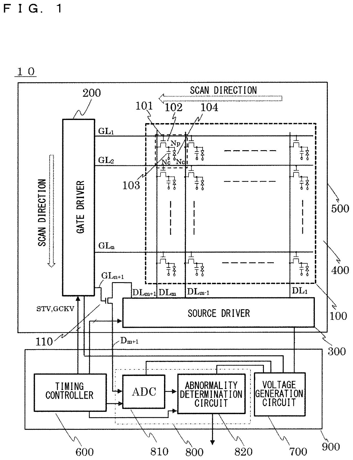
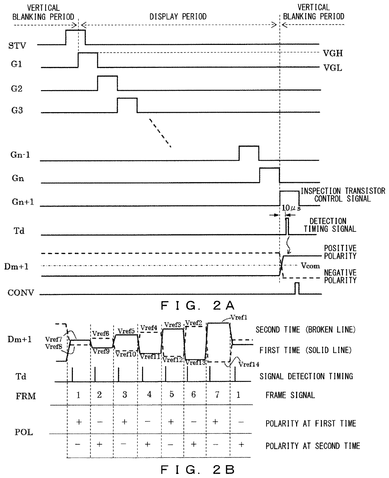
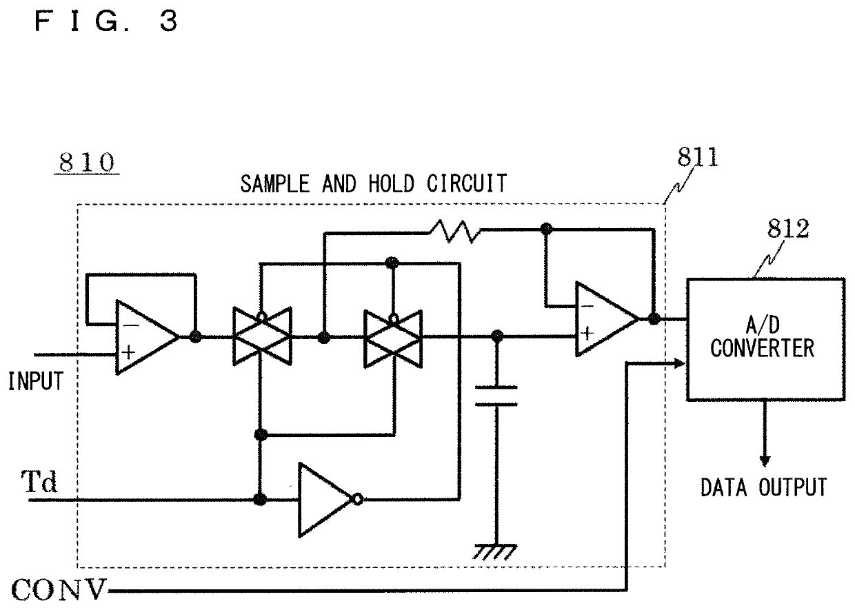
[0021]FIG. 1 is a schematic block diagram illustrating a configuration of a display apparatus according to the present disclosure, and illustrates a configuration of a liquid crystal display apparatus 10 that employs a liquid crystal panel 500 as a representative example of the display apparatus. As illustrated in FIG. 1, the display apparatus according to the present preferred embodiment includes a display panel 500, a liquid crystal drive substrate 900, and an FPC (not shown) that connects both of the display panel 500 and liquid crystal drive substrate 900. The liquid crystal drive substrate 900 includes therein a timing controller 600, a voltage generation circuit 700, an analog digital conversion circuit 810 (denoted as ADC), and an abnormality detection circuit unit 800. The display panel 500 includes: an array substrate 400 including a liquid crystal display unit 100 (display region), a gate driver IC 200 (scanning signal line drive circuit), and a source driver IC 300 (image...
second preferred embodiment
[0050]FIG. 5 is a schematic block diagram illustrating a configuration of a display apparatus according to a second preferred embodiment. Other configurations and operations are similar to those in the above-described first preferred embodiment, and therefore detailed description thereof will be omitted here.
[0051]As illustrated in FIG. 5, in the second preferred embodiment, the control electrode of the inspection transistor 110 arranged at the lower right corner of the array substrate 400 is connected to the n-th gate line GLn, and the source electrode is connected to the m+1-th output stage DLm+1. As a result, unlike the above-described first preferred embodiment, the n+1-th output stage number of the gate driver IC 200 is not necessary, and it is not necessary to increase the number of output stages driven by the gate driver IC 200 to the resolution n or more. Furthermore, since the inspection transistor 110 can be manufactured in the array process, it is not necessary to add a d...
third preferred embodiment
[0054]FIG. 6 is a schematic block diagram illustrating a configuration of a display apparatus according to a third preferred embodiment. In the present preferred embodiment, the liquid crystal display unit 100 has a configuration in which the inspection transistors 110 is arranged in correspondence with reverse scanning in the direction from lower side toward the upper side. Other configurations and operations are similar to those in the above-described first preferred embodiment, and therefore detailed description thereof will be omitted here.
[0055]As illustrated in FIG. 6, also in the third preferred embodiment, the control electrode of the inspection transistor 110 arranged at the upper right corner of the array substrate 400 is connected to the n-th gate line GLn, and the source electrode is connected to the m+1-th output stage DLm+1. As a result, unlike the above-described first preferred embodiment, the n+1-th output stage number of the gate driver IC 200 is not necessary, and...
PUM
| Property | Measurement | Unit |
|---|---|---|
| voltage stabilization time | aaaaa | aaaaa |
| voltage | aaaaa | aaaaa |
| time | aaaaa | aaaaa |
Abstract
Description
Claims
Application Information
 - R&D
- Intellectual Property
- Life Sciences
- Materials
- Tech Scout
- Unparalleled Data Quality
- Higher Quality Content
- 60% Fewer Hallucinations
Browse by: Latest US Patents, China's latest patents, Technical Efficacy Thesaurus, Application Domain, Technology Topic, Popular Technical Reports.
© 2025 PatSnap. All rights reserved.Legal|Privacy policy|Modern Slavery Act Transparency Statement|Sitemap|About US| Contact US: help@patsnap.com


