Wireless communication method, base station apparatus and wireless communication system

a wireless communication system and wireless communication technology, applied in the field of wireless communication system, base station apparatus and wireless communication method, can solve the problems of deteriorating throughput characteristic, difficult to transmit bandwidth request message with a short delay time, and difficult to always guarantee the transmission of preferential class regardless

Active Publication Date: 2011-01-13
NIPPON TELEGRAPH & TELEPHONE CORP
View PDF8 Cites 15 Cited by
  • Summary
  • Abstract
  • Description
  • Claims
  • Application Information

AI Technical Summary

Benefits of technology

[0028]According to the present invention, the wireless terminal device can transmit a bandwidth request message to request a bandwidth used for a given event such as an event with an immediacy requirement to the base station apparatus with a short delay time.

Problems solved by technology

Further, the wireless terminals in such a network are driven by a battery and are low-power and low-performance terminals having only a minimum number of functions such as data measurement and transmission.
However, in the dynamic slot assignment method using the random access, particularly, when there are a number of wireless terminals under a base station, Rch is highly likely to collide with another Rch, which causes overhead.
The overhead is the transmission deferred time caused by the exponential back off algorithm, which deteriorates a throughput characteristic.
Accordingly, when a bandwidth request message for a bandwidth used for the event with an immediacy requirement is transmitted from the wireless terminal to the base station, it is difficult to transmit the bandwidth request message with a short delay time.
However, since the method uses a random access area for two classes, it is difficult to always guarantee the transmission of the preferential class regardless of the traffic in the non-preferential class.
However, since effects of traffic in the non-preferential class cannot be ignored, it is difficult to always guarantee a transmission with a short delay time for the preferential class.

Method used


Image

  • Wireless communication method, base station apparatus and wireless communication system
  • Wireless communication method, base station apparatus and wireless communication system
  • Wireless communication method, base station apparatus and wireless communication system

Examples


first embodiment

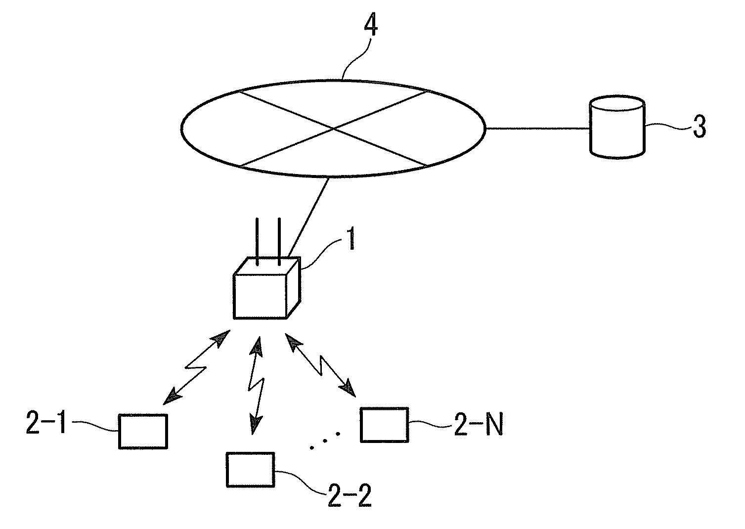
[0054]FIG. 1 is a schematic block diagram showing a wireless communication system according to a first embodiment of the present invention. The wireless communication system includes a base station 1, and wireless terminals 2−1 to 2−N (hereinafter, referred to as a wireless terminal 2 as a representative of the wireless terminals). The base station is also referred to as a base station apparatus. The wireless terminal is also referred to as a wireless terminal device. The base station 1 is connected to a wired network 4. A server 3 is also connected to the wired network 4. The base station 1 can communicate with the server 3 via the wired network 4.

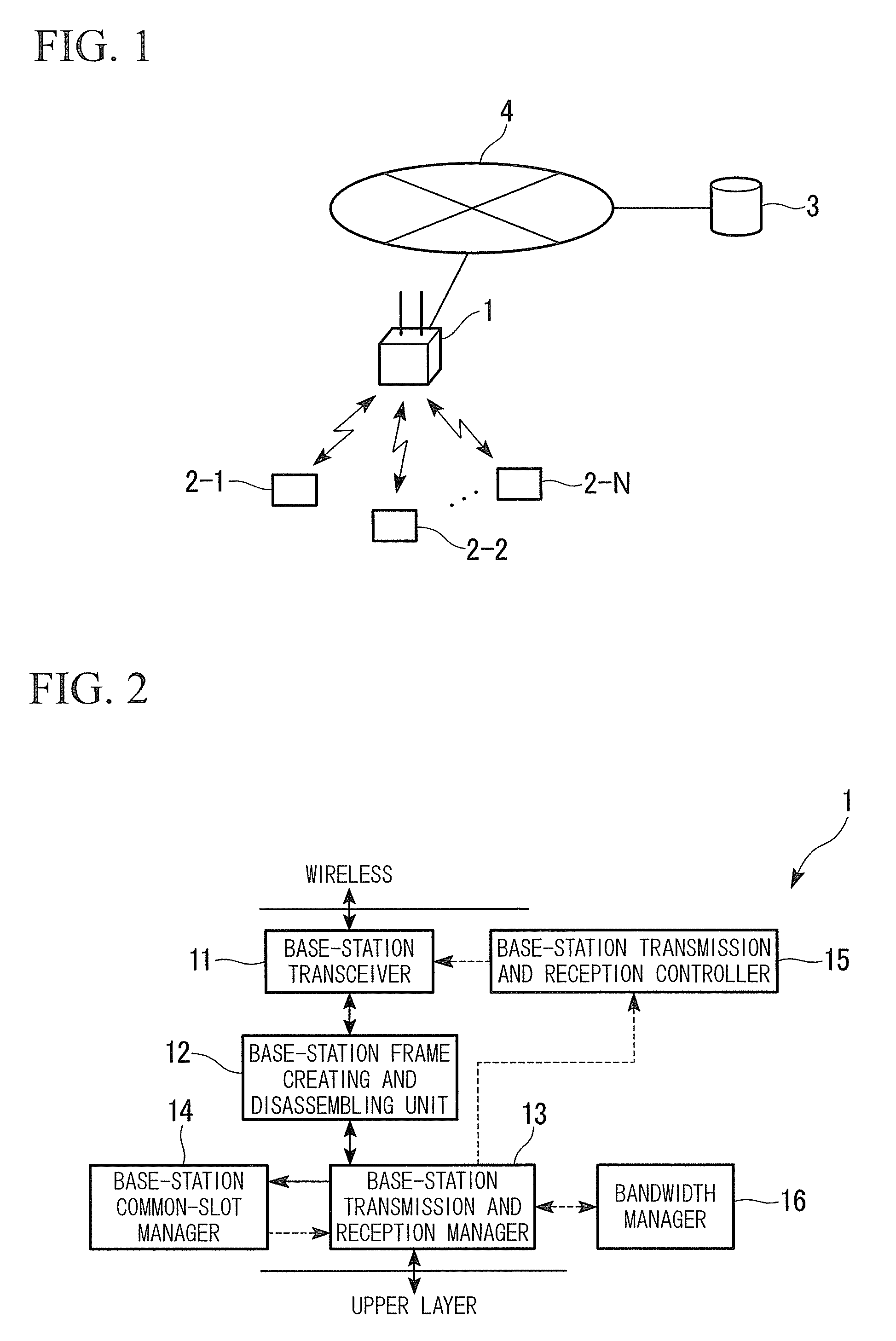
[0055]Next, a configuration of the base station 1 of the present embodiment will be described. FIG. 2 is a functional block diagram showing a configuration of the base station 1 according to the first embodiment of the present invention. The base station 1 includes a base-station transceiver 11, a base-station frame creating and disassemb...

first concrete example

[0100]A method of determining the number of preferential RA in the first concrete example will be described with reference to FIG. 13. FIG. 13 is a flowchart showing a procedure of determining the number of preferential RA in the base station 1 in the present concrete example. In the present concrete example, the number of common slot for the preferential class is 1. Further, it is assumed that the common slot is received by a reception frame #N.

[0101](Step S1301) The base-station transmission and reception manager 23 determines whether there is an access to the common slot or not. If it is determined that there is an access to the common slot, the process proceeds to step S1302, otherwise, the process proceeds to step S1307. The determination is made using the method shown in steps S201 to S208.

[0102](Step S1302) The base-station transmission and reception manager 23 determines whether the number of the preferential RA in previous frame #(N−1) was 0 or not. If it is determined that...

second concrete example

[0127]A method of determining the number of preferential RA in a second concrete example will be described with reference to FIG. 16. FIG. 16 is a flowchart showing a procedure of determining the number of preferential RA in a base station 1 in the present concrete example. In the present concrete example, processing varies according to three types of accesses: “there is no access to a common slot,”“there is an access to a common slot from one wireless terminal,” and “there is an access to a common slot from two or more wireless terminals” as the result of accessing the common slot.

[0128]In the present concrete example, the number of common slot for the preferential class is 1. Further, it is assumed that the common slot is received by a reception frame #N. In the present concrete example, a configuration of a frame transmitted using the common slot is the same as shown in FIG. 5B.

[0129](Step S1601) The base-station transmission and reception manager 23 determines whether there is a...


PUM


Abstract

A base station apparatus includes a base-station receiver which receives information indicating the occurrence of the given event in the wireless terminal device, the information being transmitted from the wireless terminal device using the common slot. The base station apparatus includes a base-station transmission and reception manager which determines the number of random slots assigned as random slots to transmit the bandwidth request information for the given event among random slots in the random access period, based on the occurrence of the given event received by the base-station receiver. The base station apparatus includes a base-station transmitter which transmits, in the base station apparatus, information on the assigned random slots to the wireless terminal device of random access period.

Description

TECHNICAL FIELD[0001]The present invention relates to a wireless communication method, a base station apparatus and a wireless communication system capable of dynamic bandwidth assignment.[0002]This application claims priority to and the benefit of Japanese Patent Applications No. 2008-046016 filed on Feb. 27, 2008, the disclosure of which is incorporated herein by reference.BACKGROUND ART[0003]In recent years, ubiquitous networks using a wireless local and personal areas communication system such as wireless tags, Bluetooth (registered trademark), and ZigBee (registered trademark) have begun to be widely used in the fields of equipment control, traffic, distribution, environmental protection, food industry, agriculture, earthquake monitoring, health care and so on. With the development of applications or services, the number of users of a network is expected to increase in the future. Here, a global ubiquitous network capable of providing several applications or services to a great...

Claims


Application Information

Patent Timeline
Patent Type & Authority Applications(United States)
IPC IPC(8): H04W72/04
CPCH04W72/0453H04W74/0833H04W74/002H04W72/1242H04W74/02H04W72/569
Inventor SHIMIZU, YOSHITAKANUNO, FUSAO
Owner NIPPON TELEGRAPH & TELEPHONE CORP
Why Eureka
Try Eureka