Delay-locked loop, voltage-controlled delay line and delay unit

A voltage-controlled delay line and delay unit technology, applied in the field of communications, to avoid clock inaccuracy and reduce layout area

Inactive Publication Date: 2015-03-25
BEIJING XINYI CENTURY TECH
View PDF4 Cites 17 Cited by
  • Summary
  • Abstract
  • Description
  • Claims
  • Application Information

AI Technical Summary

Problems solved by technology

[0007] this kind figure 2 The delay unit of the structure can only be used when the clock is relatively slow, and when the clock frequency reaches hundreds of MHZ or even GHz, it will be powerless

Method used


Image

  • Delay-locked loop, voltage-controlled delay line and delay unit
  • Delay-locked loop, voltage-controlled delay line and delay unit
  • Delay-locked loop, voltage-controlled delay line and delay unit

Examples


Embodiment Construction

[0028] The following will clearly and completely describe the technical solutions in the embodiments of the present invention with reference to the accompanying drawings in the embodiments of the present invention. Obviously, the described embodiments are only some, not all, embodiments of the present invention. Based on the embodiments of the present invention, all other embodiments obtained by persons of ordinary skill in the art without creative efforts fall within the protection scope of the present invention.

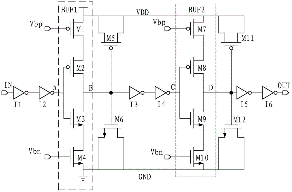
[0029] Please refer to image 3 , is a circuit structure diagram of an embodiment of the delay unit provided by the embodiment of the present invention.

[0030] like image 3 As shown, the delay unit includes: MOS transistors M1 to M12 and inverters I1 to I6. Among them, M1, M2, M5, M7, M8, and M11 are PMOS tubes, and M3, M4, M6, M9, M10, and M12 are NMOS tubes.

[0031] Wherein, M1 to M6 and M7 to M12 constitute the same structure, that is, a current starving ...


PUM


Abstract

The embodiment of the invention discloses a delay unit, a voltage-controlled delay line and a delay-locked loop. The delay unit comprises multiple current hunger buffers connected in series. Load capacitors are connected between output of each current hunger buffer and a power voltage and between the output and the ground respectively in series. The voltage-controlled delay line is formed by cascading one or more delay units. The delay-locked loop comprises an offset generation circuit and the voltage-controlled delay line, the offset generation circuit outputs voltage control signals Vbp and Vbn controlling the voltage-controlled delay line, and the voltage-controlled delay line comprises an internal voltage-controlled delay line for phase locking and one or more parallel external voltage-controlled delay lines providing delay clocks, wherein the internal voltage-controlled delay line and the external voltage-controlled delay lines each comprise one or more cascaded delay units. The delay unit, the voltage-controlled delay line and the delay-locked loop are suitable for high-speed circuits, connecting lines on the high-speed clocks can be reduced through the delay-locked loop, and the problem that clock accuracy is insufficient due to the fact that the connecting lines are long is solved.

Description

technical field [0001] The invention relates to the communication field, in particular to a delay-locked loop, a voltage-controlled delay line and a delay unit. Background technique [0002] In data transmission, as the amount of data transmission increases, the clock frequency becomes higher and higher, and the requirements for synchronous clocks become more and more stringent. In order to increase the data transmission rate, the easy way is to use the rising and falling edges of the clock to collect data at the same time, so as to double the efficiency at the same rate. In addition, during data processing, clocks with different phases are also required, for example: 45° phase clocks or 90° phase clocks, etc., and these clocks are required to maintain a good duty cycle. Currently, the generation of these phase clocks can be implemented by a DLL (Delay Locked Loop, delay locked loop). [0003] figure 1 shows the structure of a typical DLL. [0004] like figure 1 As show...

Claims


Application Information

Patent Timeline
Patent Type & Authority Applications(China)
IPC IPC(8): H03L7/06
Inventor 罗庆华田学红李仕胜李仕炽张海霞董晓军
Owner BEIJING XINYI CENTURY TECH
Why Eureka
Try Eureka