Motor drive circuit
a technology of motor drive and circuit, which is applied in the direction of motor/generator/converter stopper, dynamo-electric converter control, instruments, etc., can solve the problems of destroying the semiconductor switching element, not being able to detect a failure of the return current circuit,
- Summary
- Abstract
- Description
- Claims
- Application Information
AI Technical Summary
Benefits of technology
Problems solved by technology
Method used
Image
Examples
first embodiment
[0027
[0028]A first embodiment of the present invention will be explained. In the present embodiment, a case will be explained in which the first embodiment of the present invention is used for a motor drive circuit for driving a motor that is provided with a brake fluid pressure control actuator or the like.
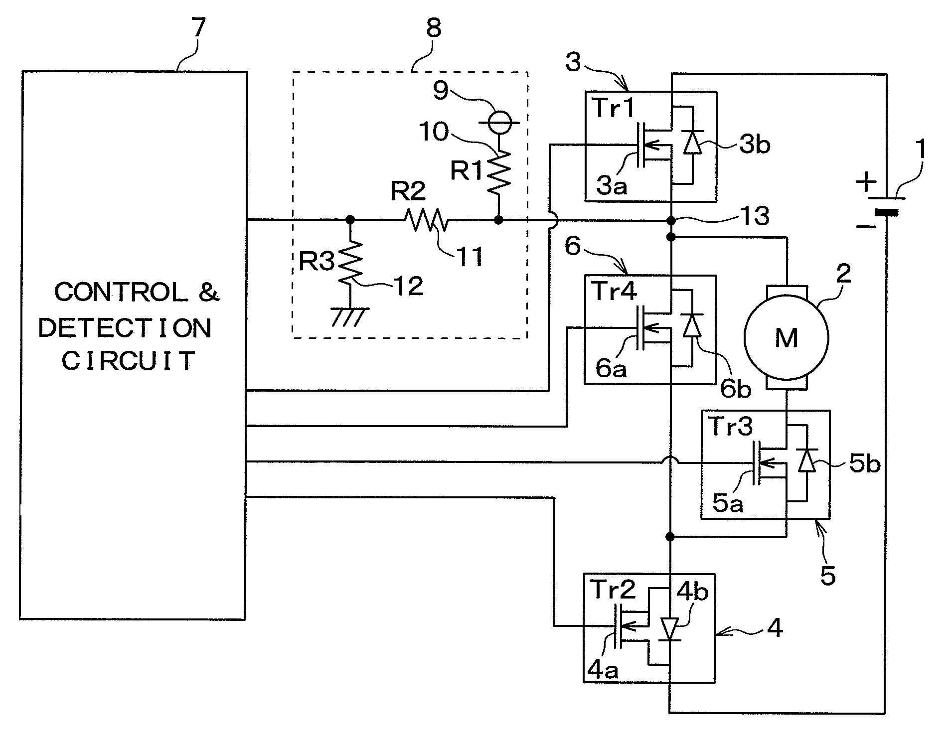
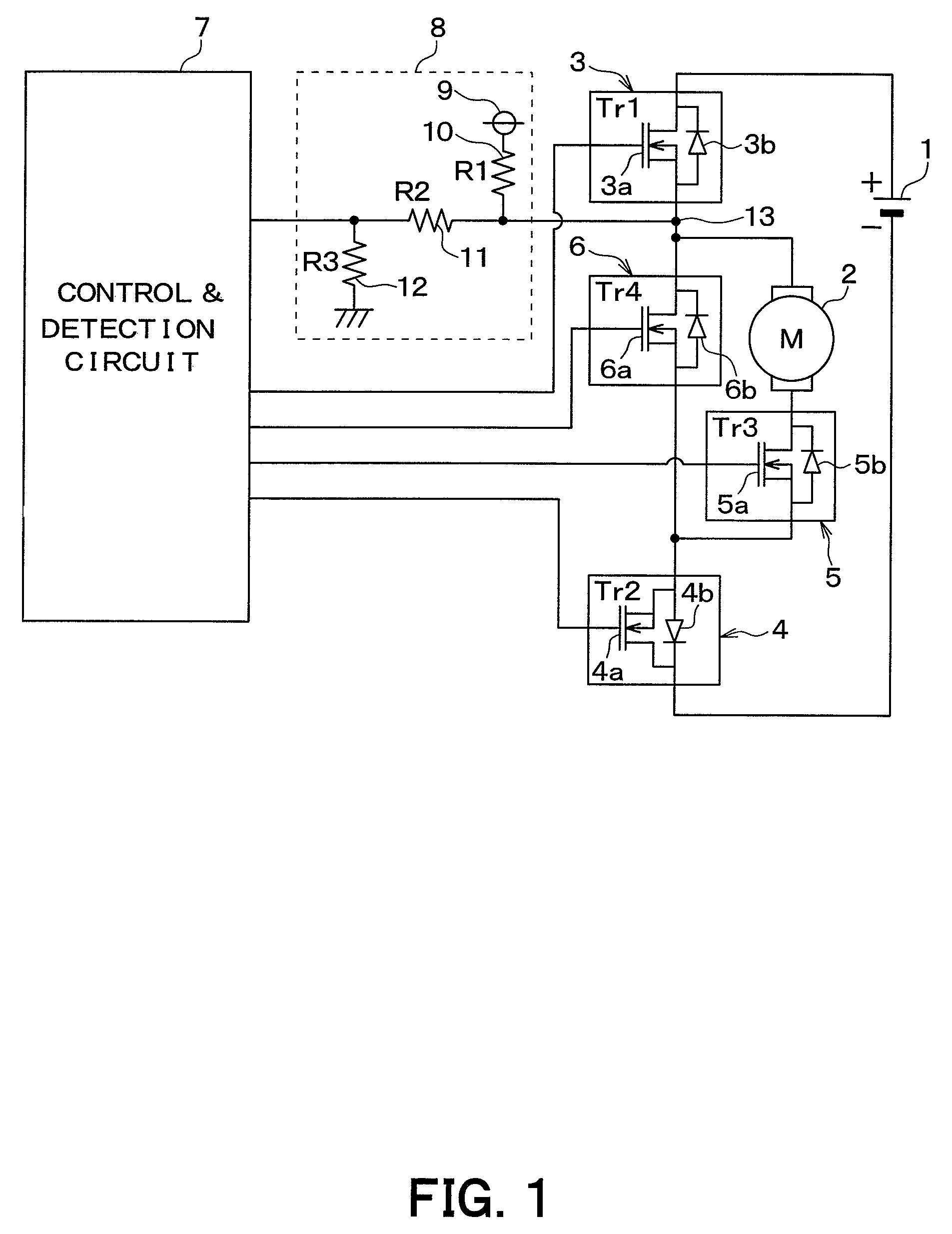
[0029]FIG. 1 is a figure that shows a circuit configuration of the motor drive circuit according to the present embodiment. As shown in this figure, a battery 1 serves as a power source, and the motor drive circuit performs driving of a motor 2 based on a supply of electric power from the battery 1.
[0030]The motor drive circuit is provided with first to fourth semiconductor switching elements 3 to 6 and a control and detection circuit 7 that serves as a control portion for controlling the first to the fourth semiconductor switching elements 3 to 6.
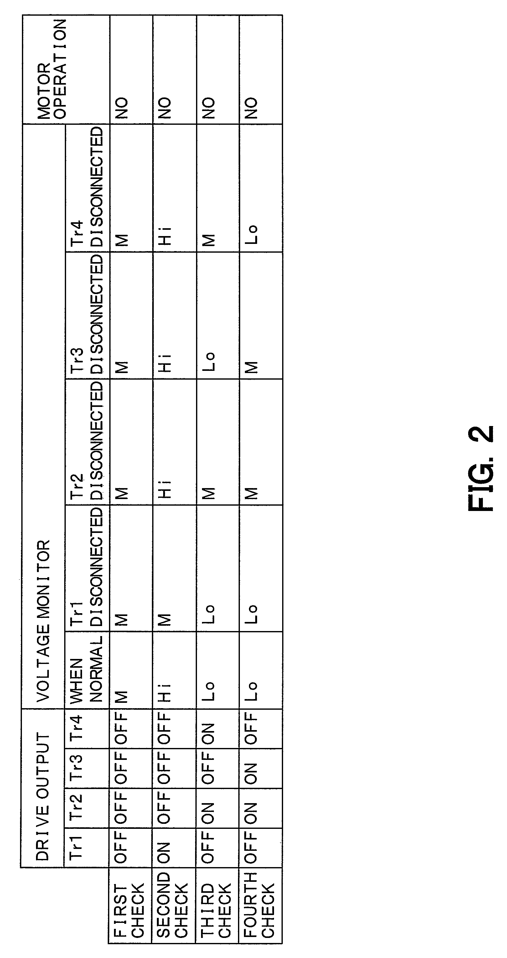
[0031]The first semiconductor switching element 3 is connected in series to the motor 2 on the upstream side of the motor 2. The first...
second embodiment
[0052
[0053]A second embodiment of the present invention will be explained. In the present embodiment, the connection configuration in the motor drive circuit is different from that in the first embodiment, but in all other respects, the present embodiment is the same as the first embodiment, so only the portions that are different will be explained.
[0054]FIG. 3 is a figure that shows a circuit configuration of the motor drive circuit according to the present embodiment. As shown in this figure, the motor drive circuit in the present embodiment is not configured as it is in the first embodiment, with the third semiconductor switching element 5 connected to the negative terminal side of the battery 1 through the second semiconductor switching element 4, but rather is configured such that the third semiconductor switching element 5 is connected directly to the negative terminal side of the battery 1. In other words, the motor drive circuit is configured such that the second semiconduct...
third embodiment
[0064
[0065]A third embodiment of the present invention will be explained. In the present embodiment, the connection configuration in the motor drive circuit is different from that in the first embodiment, but in all other respects, the present embodiment is the same as the first embodiment, so only the portions that are different will be explained.
[0066]FIG. 5 is a figure that shows a circuit configuration of the motor drive circuit according to the present embodiment. As shown in this figure, the motor drive circuit in the present embodiment is configured such that the second semiconductor switching element 4 is located within the return current circuit, and while the third semiconductor switching element 5 is located outside the return current circuit, it is located on the downstream side of the second semiconductor switching element 4.
[0067]In this sort of configuration, each of the semiconductor switching elements 3 to 6 functions in basically the same manner as in the first emb...
PUM
 Abstract
Description
Claims
Application Information
 - R&D
- Intellectual Property
- Life Sciences
- Materials
- Tech Scout
- Unparalleled Data Quality
- Higher Quality Content
- 60% Fewer Hallucinations
Browse by: Latest US Patents, China's latest patents, Technical Efficacy Thesaurus, Application Domain, Technology Topic, Popular Technical Reports.
© 2025 PatSnap. All rights reserved.Legal|Privacy policy|Modern Slavery Act Transparency Statement|Sitemap|About US| Contact US: help@patsnap.com


