Method and system for non-destructively evaluating a hidden workpiece

a workpiece and workpiece technology, applied in the field of methods and systems for non-destructive evaluation of workpieces, can solve the problems of significant aircraft downtime at a repair depot, remote locations of structural assemblies, and prone to corrosion in remote locations, so as to achieve the effect of without disassembly and without significant disassembly

Active Publication Date: 2015-02-26
THE BOEING CO
View PDF4 Cites 5 Cited by
  • Summary
  • Abstract
  • Description
  • Claims
  • Application Information

AI Technical Summary

Benefits of technology

[0007]A method and system for non-destructively evaluating a workpiece hidden by an overlying structure are provided in accordance with an example embodiment of the present disclosure. In this regard, the method and system of one embodiment rely upon backscattered radiation such that access is only required to one side of the workpiece that is to be inspected. As such, a workpiece may be inspected in a non-destructive manner without disassembly or, at least, without significant disassembly, while requiring access to only one side of the workpiece. By relying upon backscattered radiation, such as backscattered x-rays, the method and system of one embodiment may detect and permit a workpiece that is hidden from view to be non-destructively inspected, thereby permitting evaluation and, if necessary, repair of the workpiece in an orderly manner.

Problems solved by technology

Although some of the structural components are readily accessible so as to be inspected visually, a number of the structural components, such as the stringers of an aircraft, are positioned in a remote location so as to be hidden from view or to otherwise be of limited access.
The removal and subsequent reattachment of the beavertail fitting following visual inspection of the portion of the wing skin that underlies the beavertail fitting increase the time that the aircraft is out of service and, as a result, may be inefficient in an instance in which the estimate of the condition of the portion of the wing skin that underlies the beavertail fitting is subsequently proven to be incorrect by the visual inspection of the portion of the wing skin that underlies the beavertail fitting.
In order to inspect these hidden structural components as opposed to relying upon an estimate of their condition, a structural assembly may be disassembled and, following inspection, may then be reassembled, thereby resulting in substantial expense and downtime.
With respect to an aircraft, for example, the disassembly, inspection and subsequent reassembly may require a number of man hours and lead to significant aircraft downtime at a repair depot.
Some remote locations of a structural assembly may be prone to corrosion as a result of the intrusion and retention of moisture.
While access to the opposite sides of a structural component to be inspected is available in some instances, the opposite sides of some structural components may not be readily accessed and, as such conventional transmission radiographic techniques may be unavailable for non-destructive inspection purposes.
Moreover, some structural components may be hidden by an overlying structure that has a thickness that is varied, thereby further complicating the radiographic inspection of the hidden structure since the results will also be dependent upon the thickness of the overlying structure through which the hidden structure was inspected.
As such, many structural assemblies must be disassembled in order to inspect the structural components that are otherwise hidden from view, thereby materially increasing the time and the labor required for the inspection.

Method used


Image

  • Method and system for non-destructively evaluating a hidden workpiece
  • Method and system for non-destructively evaluating a hidden workpiece
  • Method and system for non-destructively evaluating a hidden workpiece

Examples


Embodiment Construction

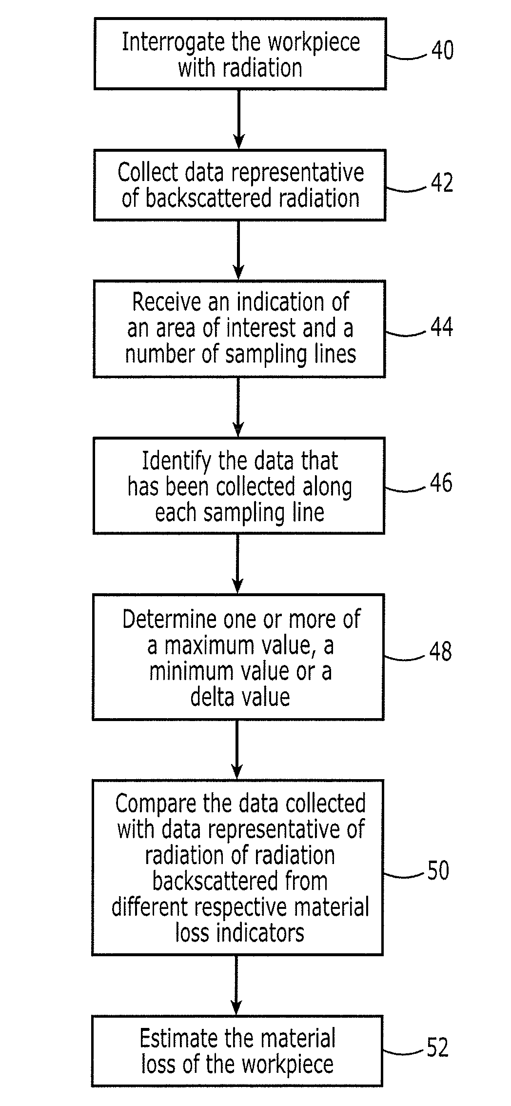
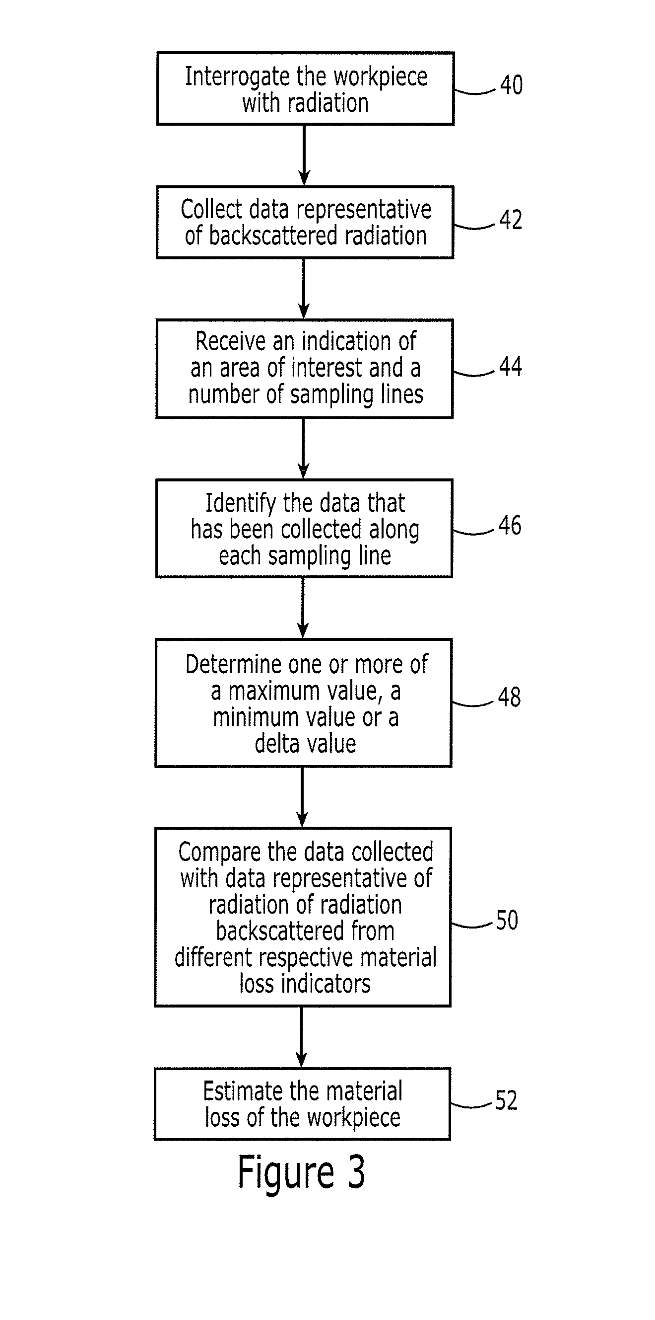
[0030]The present disclosure now will be described more fully with reference to the accompanying drawings, in which some, but not all embodiments of the invention are shown. This disclosure may be embodied in many different forms and should not be construed as limited to the embodiments set forth; rather, these embodiments are provided so that this disclosure will be thorough and complete, and will fully convey the scope of the invention to those skilled in the art. Like numbers refer to like elements throughout.

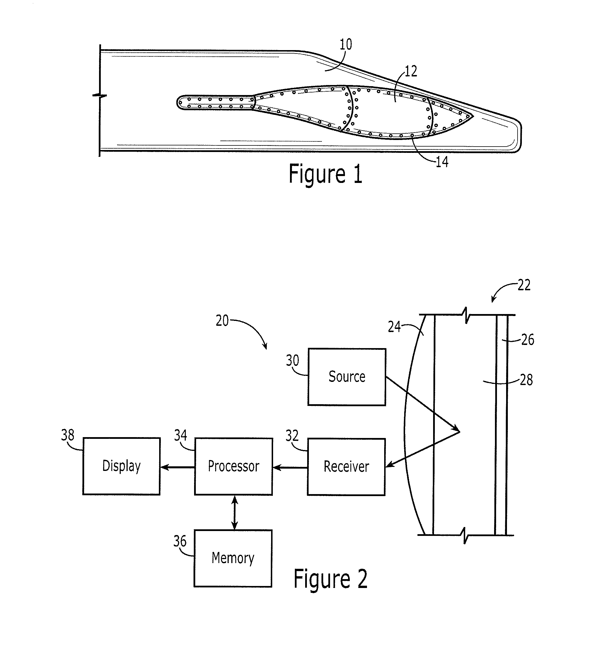
[0031]A method and system are provided for non-destructively evaluating a workpiece hidden by an overlying structure. As used herein, a workpiece is hidden if all or a portion of the workpiece is hidden from view, that is, visually hidden, absent disassembly of a structural assembly including the workpiece. A variety of workpieces may be non-destructively evaluated. In this regard, the workpiece may be a structural component of a wide variety of different structural assembli...


PUM

PropertyMeasurementUnit
lengthaaaaaaaaaa
thicknessaaaaaaaaaa
thicknessaaaaaaaaaa

Abstract

A method and system are provided for non-destructively evaluating a workpiece hidden by an overlying structure. In the context of a method, a workpiece is interrogated with radiation, such as x-ray radiation, that also propagates through the overlying structure. The method further includes collecting data representative of radiation backscattered from the workpiece. Based upon a thickness and material of the overlying structure, the method compares the data that has been collected from the workpiece with reference data representative of radiation backscattered from a standard that includes different respective material loss indicators hidden by an overlying structure of the same thickness and material. Each material loss indicator is a physical representation of a different amount of material loss. As a result of the comparison, the method estimates the material loss of the workpiece.

Description

CROSS-REFERENCE TO RELATED APPLICATION[0001]This application claims the benefit of and is a continuation-in-part of U.S. patent application Ser. No. 13 / 527,068, filed Jun. 19, 2012, the contents of which is incorporated by reference herein in its entirety.TECHNOLOGICAL FIELD[0002]An example embodiment of the present disclosure relates generally to a method and system for non-destructively evaluating a workpiece hidden by an overlying structure.BACKGROUND[0003]It is oftentimes desirable to inspect a workpiece in order to detect anomalies, such as the effects of corrosion. For example, vehicles, such as aircraft, trains, automobiles and other motor vehicles, and other structures may include a number of structural components that are desirably inspected in order to identify anomalies, such as the effects of corrosion. Although some of the structural components are readily accessible so as to be inspected visually, a number of the structural components, such as the stringers of an aircr...

Claims


Application Information

Patent Timeline
Patent Type & Authority Applications(United States)
IPC IPC(8): G01N23/203G01B15/02
CPCG01B15/02G01N23/203G01N17/043
Inventor ENGELBART, ROGER W.LOU, TAISIA TSUKRUK
Owner THE BOEING CO
Why Eureka
Try Eureka