Image forming apparatus and process cartridge

a technology of image forming apparatus and process cartridge, which is applied in the direction of electrographic process apparatus, instruments, optics, etc., can solve the problems of difficult to ensure a mounting locus, and achieve the effects of shortening the fpot, improving usability, and reducing the size of the image forming apparatus

Inactive Publication Date: 2015-02-26
CANON KK
View PDF3 Cites 17 Cited by
  • Summary
  • Abstract
  • Description
  • Claims
  • Application Information

AI Technical Summary

Benefits of technology

[0006]A principal object of the present invention is to realize a state in which even under a condition such that adjacent two cartridges partly overlap with each other at an image formable position inside an apparatus main assembly of an image forming apparatus, a movable member for supporting the cartridges is pulled out to an outside of the apparatus main assembly to make the cartridges detachably mountable to the movable member. As a result, there is provided an image forming apparatus capable of improving usability and also capable of not only shortening FPOT but also downsizing the image forming apparatus.

Problems solved by technology

In such cases, it can be difficult to ensure a mounting locus along which an intended process cartridge is detachably mountable in the vertical direction.

Method used


Image

  • Image forming apparatus and process cartridge
  • Image forming apparatus and process cartridge
  • Image forming apparatus and process cartridge

Examples


embodiment 1

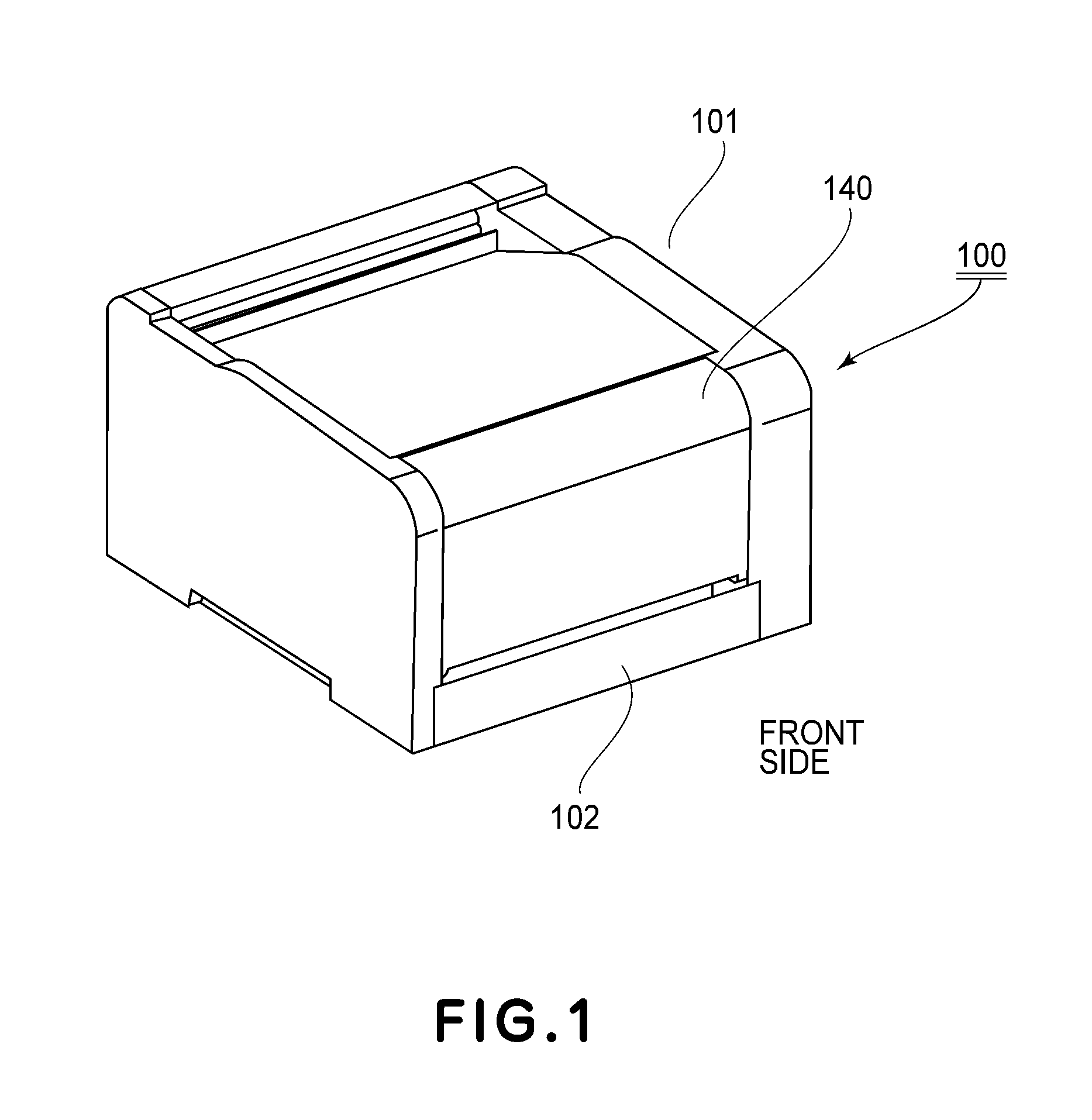
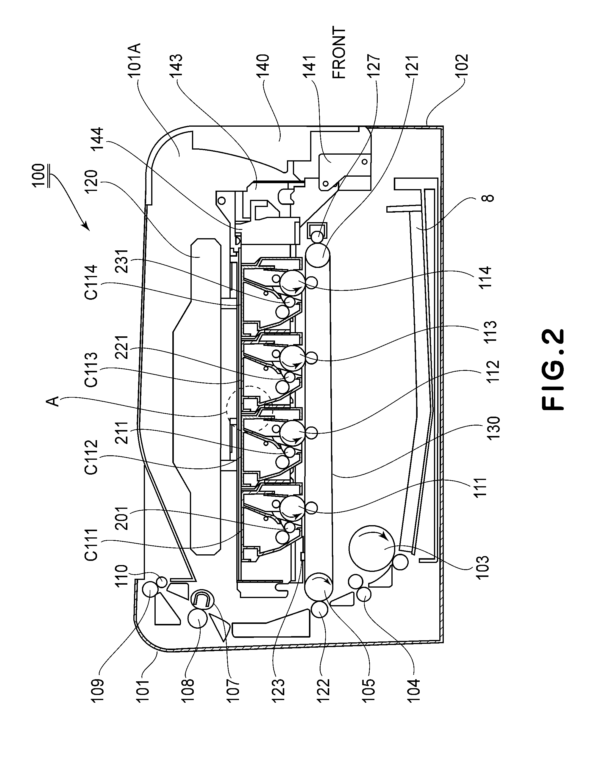
[0031]Embodiment 1 of the present invention will be described with reference to FIGS. 1-12. Description will be made in the order of a general structure of an image forming apparatus, a mounting and dismounting method of a process cartridge, a structure of the process cartridge and a slide movement constitution of a cartridge.

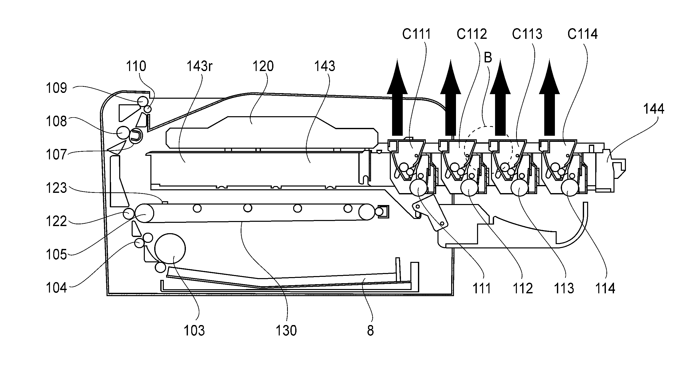
[0032]In this embodiment, as the image forming apparatus, an electrophotographic laser beam printer capable of forming a color image on a recording material is illustrated. Further, as the image forming apparatus, an image forming apparatus in which respective color toner images on photosensitive drums are successively transferred onto a belt (intermediary recording medium) and then are collectively transferred from the belt onto a recording material as a final recording medium is illustrated.

[0033]In this embodiment, a position where an image is formed on the photosensitive drum in contact with an intermediary transfer belt is defined as an “image forming posi...

embodiment 2

[0102]Embodiment 2 of the present invention will be described with reference to FIGS. 13-20. In this embodiment, constituent elements similar to the above-described constituent elements in Embodiment 1 will be omitted from description by adding the same reference numerals or symbols. In this embodiment, first to fourth process cartridges C211, C212, C213 and C214, and a cartridge tray 244 are used.

(Structure of Process Cartridge)

[0103]In this embodiment, the first to fourth process cartridges C211-C214 have the same contact developing method constitution.

[0104]That is, at the image forming position 100, the developing roller 201 in the developing unit 156 contacts the photosensitive drum 111 by using unshown flange member S. Further, other basic constitutions include the photosensitive member unit 151, the developing unit 156, the left side cover 152L and the right side cover 153R similarly as in Embodiment 1.

[0105]A general structure of each process cartridge C in this embodiment w...

embodiment 3

[0137]Embodiment 3 of the present invention will be described with reference to FIGS. 21 and 22. In this embodiment, constituent elements similar to the above-described constituent elements in Embodiments 1 and 2 will be omitted from description by adding the same reference numerals or symbols. In this embodiment, a cartridge tray 344 is used.

(Development Contact-and-Separation Constitution and Slide Movement Constitution of Cartridge)

[0138]With reference to FIGS. 21 and 22, the development contact-and-separation constitution and slide movement constitution as features of this embodiment will be described. FIG. 21 is a perspective view of an outer appearance of the cartridge tray 344. In FIG. 22, (a) to (c) are side views of outer appearances of the cartridge tray 344 with the pulling-out operation.

[0139]As shown in FIG. 22, each of the left and right tray holding members 143 is provided with a lift member 404 in the inside of the apparatus main assembly. As shown in (a) of FIG. 22,...


PUM


Abstract

An image forming apparatus, to which process cartridges each including a photosensitive drum and a developing roller, includes: a movable member movable between an inside and an outside of a main assembly of the image forming apparatus in a movement direction crossing a longitudinal direction of the photosensitive drum; a mounting portion for supporting the process cartridges, wherein the process cartridges are detachably mountable to the mounting portion from a direction crossing the longitudinal direction and the movement direction; and an interrelating member, movable in interrelation with movement of the movable member, for moving the developing roller relative to the photosensitive drum so that a distance between a rotation center of the photosensitive drum and a rotation center of the developing roller is decreased with respect to the movement direction when the movable member is moved from the inside to the outside of the main assembly.

Description

FIELD OF THE INVENTION AND RELATED ART[0001]The present invention relates to an image forming apparatus, to which a plurality of process cartridges and detachably mountable, for forming a color image on a recording material (medium) and relates to the process cartridge.[0002]Here, the image forming apparatus is an apparatus for forming the image on the recording material by using an image forming process. The image forming apparatus includes, e.g., a copying machine, a printer (a laser (beam) printer, an LED printer, or the like), a facsimile machine, an image display apparatus (electronic blackboard or electronic white board) and the like. On the recording material, the image is formed by the image forming apparatus, and the recording material may include, e.g., a sheet, an OHT sheet, an intermediary transfer member, an image displaying material, and the like.[0003]Mounting and dismounting of the process cartridge relative to the image forming apparatus will be described. In an ele...

Claims


Application Information

Patent Timeline
Patent Type & Authority Applications(United States)
IPC IPC(8): G03G15/00G03G21/18
CPCG03G21/1807G03G21/1842G03G21/1623G03G2221/1678G03G15/0178G03G21/1633G03G21/1821G03G21/1853G03G2221/1684G03G21/1676
Inventor HOASHI, SHIGERUSATO, MASAKI
Owner CANON KK
Why Eureka
Try Eureka