Wire collection device for stent delivery system

a technology of stent delivery and wire collection, which is applied in the field of wire collection devices, can solve the problems of inaccurate stent positioning, large amount of force, and inability to maintain the position of the inner catheter while pulling on the outer sheath, and achieve the effect of increasing the collection diameter of the retraction wir

Active Publication Date: 2015-02-26
COOK MEDICAL TECH LLC
View PDF0 Cites 15 Cited by
  • Summary
  • Abstract
  • Description
  • Claims
  • Application Information

AI Technical Summary

Benefits of technology

[0007]In one aspect, a stent delivery system includes a wire collection device with a plurality of nested wire collection drums, a retraction wire, a thumbwheel, and a catching mechanism. The plurality of nested wire collection drums include a first drum concentric in a second drum. The inner diameter of the second drum is larger than the outer diameter of the first drum. The retraction wire is attached to the first drum and extends through a slot of the second drum. The thumbwheel is coupled to the first drum and can be rotated to actuate rotation of the first drum to collect the retraction wire around the diameter of the first drum. The retraction wire can be connected to a proximal end of an outer sheath of the stent delivery system. The catching mechanism can rotate about the first drum so as to engage a catch portion of the second drum to actuate rotation of the second drum. This collects the retraction wire around an outer diameter of the second drum, and increases the collection diameter of the retraction wire and provides a mechanical advantage for sheath retraction.
[0008]In another aspect, a method for collecting a retraction wire in a stent delivery system includes rotating a thumbwheel that is coupled to a plurality of nested wire collection drums. A first drum is concentric in a second drum. The inner diameter of the second drum is larger than a diameter of the inner drum. A slot in the second drum is configured to allow a retraction wire to pass through the second drum to the first drum. Rotating the thumbwheel actuates rotation of the inner drum and actuates rotation of a catching mechanism. Rotation of the inner drum collects the retraction wire around the diameter of the first drum. The retraction wire is coupled to a proximal end of an outer sheath of the stent delivery system. Collecting the retraction wire retracts the outer sheath to deploy a self-expanding stent. The catching mechanism can be rotated about the first until the catching mechanism engages a catch portion of the second drum, which actuates rotation of the second drum to collect the retraction wire around an outer diameter of the second drum. This increases the collection diameter of the retraction wire to provide a mechanical advantage.
[0009]In another aspect, a handle of a stent delivery system includes a wire collection device with a plurality of concentrically nested wire collection drums, a retraction wire, a thumbwheel, a first catching mechanism and a second catching mechanism. The plurality of concentrically nested wire collection drums includes an inner drum that is concentric in a first outer drum and a second outer drum. The inner diameter of the first outer drum is larger than the outer diameter of the inner drum. The inner diameter of the second outer drum is larger than the outer diameter of the first outer drum. The retraction wire is attached to the inner drum and extends through a slot of the second outer drum and a slot of the first outer drum. The thumbwheel is coupled to the inner drum. The thumbwheel can be rotated to actuate rotation of the inner drum to collect the retraction wire around the outer diameter of the inner drum. A distal end of the retraction wire is connected to a proximal end of an outer sheath of the stent delivery system. The first catching mechanism can be rotated about the inner drum and engage a catch portion of the first outer drum to actuate rotation of the first outer drum. The first outer drum can engage the retraction wire to cause the retraction wire to collect around the outer diameter of the first outer drum. This increases the collection diameter of the retraction wire to increase a mechanical advantage. The second catching mechanism can be rotated about the first outer drum and engage a catch portion of the second outer drum. This actuates rotation of the second drum until it engages the retraction wire, causing the retraction wire to collect around an outer diameter of the second collection drum. This further increases the collection diameter of the retraction wire to further increase the mechanical advantage.

Problems solved by technology

In these “pin and pull” systems, the user has difficulty maintaining the position of the inner catheter while pulling on the outer sheath because of resistance between the inner catheter and outer sheath, between the outer sheath and the stent, and between the outer sheath and the surrounding vascular walls, or other surrounding blood vessel or body vessel.
To overcome this resistance the user may need to exert a large amount of force that leads to various complications, including for example, inaccurate stent positioning, displacement of the stent, shortening or lengthening of the stent, or other damage to the structure of the stent, or damage to the target vessel.
“Pin and pull” systems may also have other disadvantages, including, for example, lack of control during stent deployment and requirement of assistance from a second person.
Thus, stent deployment is difficult to control because the required deployment force varies as the outer sheath retracts across the surface of the stent.
In most pin and pull systems, the ratio of handle movement to stent deployment distance is 1:1, requiring the user to move faster to deploy longer stents and increasing difficulty in controlling the stent.
Because the user's hands are holding the distal ends of the outer sheath and inner catheter, the user cannot easily monitor or attend to the positioning of the outer sheath in the hemostasis valve to ensure accurate stent placement, such that an assistant must be present to attend to the positioning of the outer sheath in the hemostasis valve and accurate positioning of the stent.
In other words, such systems do not provide mechanical advantage to accommodate, or reduce the amount of work required for, deployment of longer stents as compared to deployment of shorter stents.

Method used


Image

  • Wire collection device for stent delivery system
  • Wire collection device for stent delivery system
  • Wire collection device for stent delivery system

Examples


Embodiment Construction

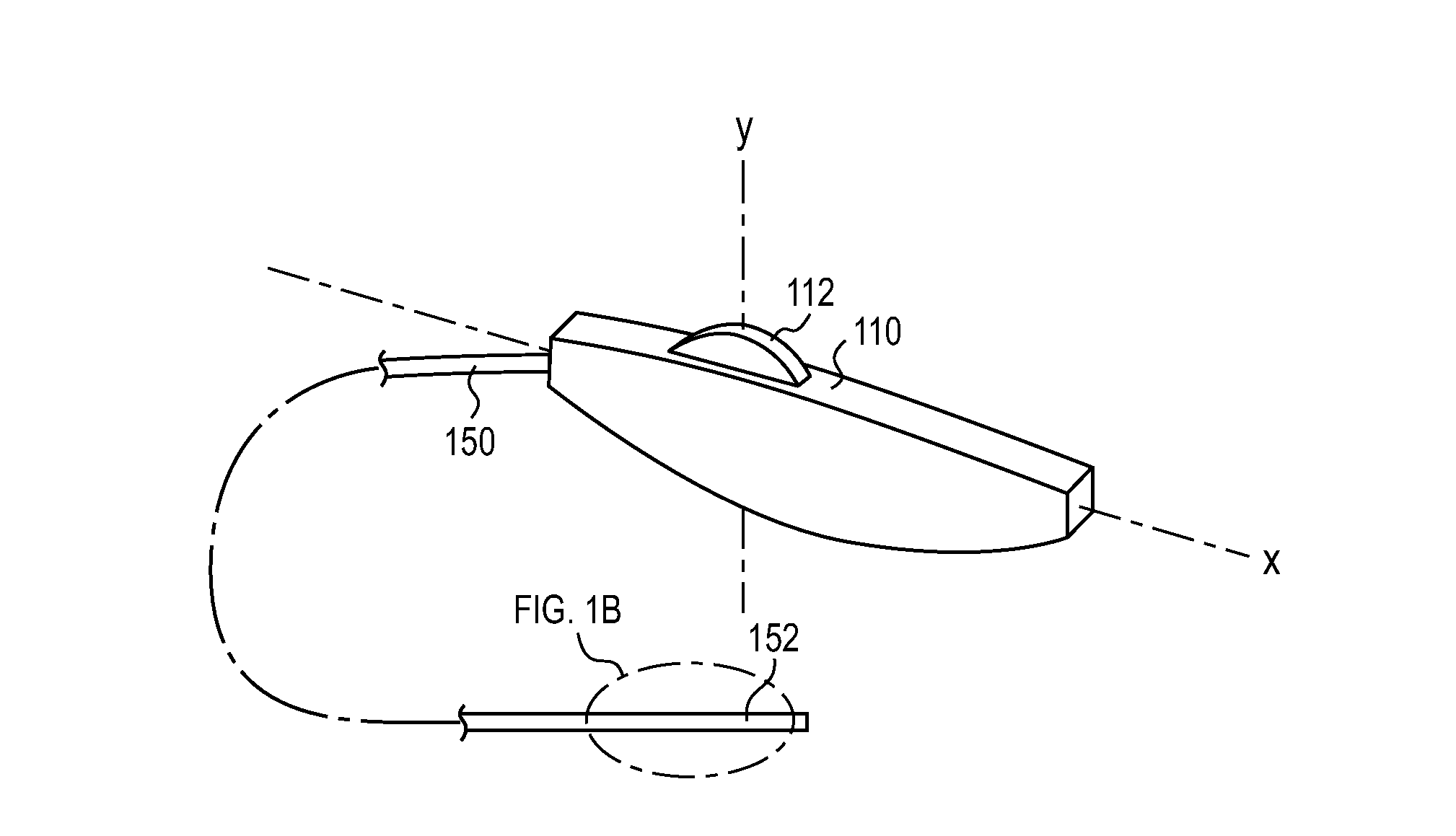
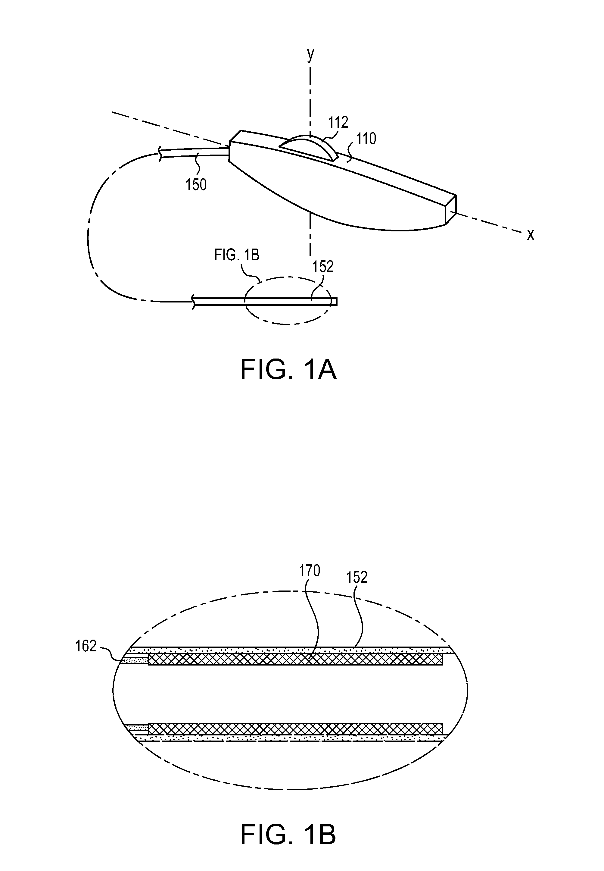
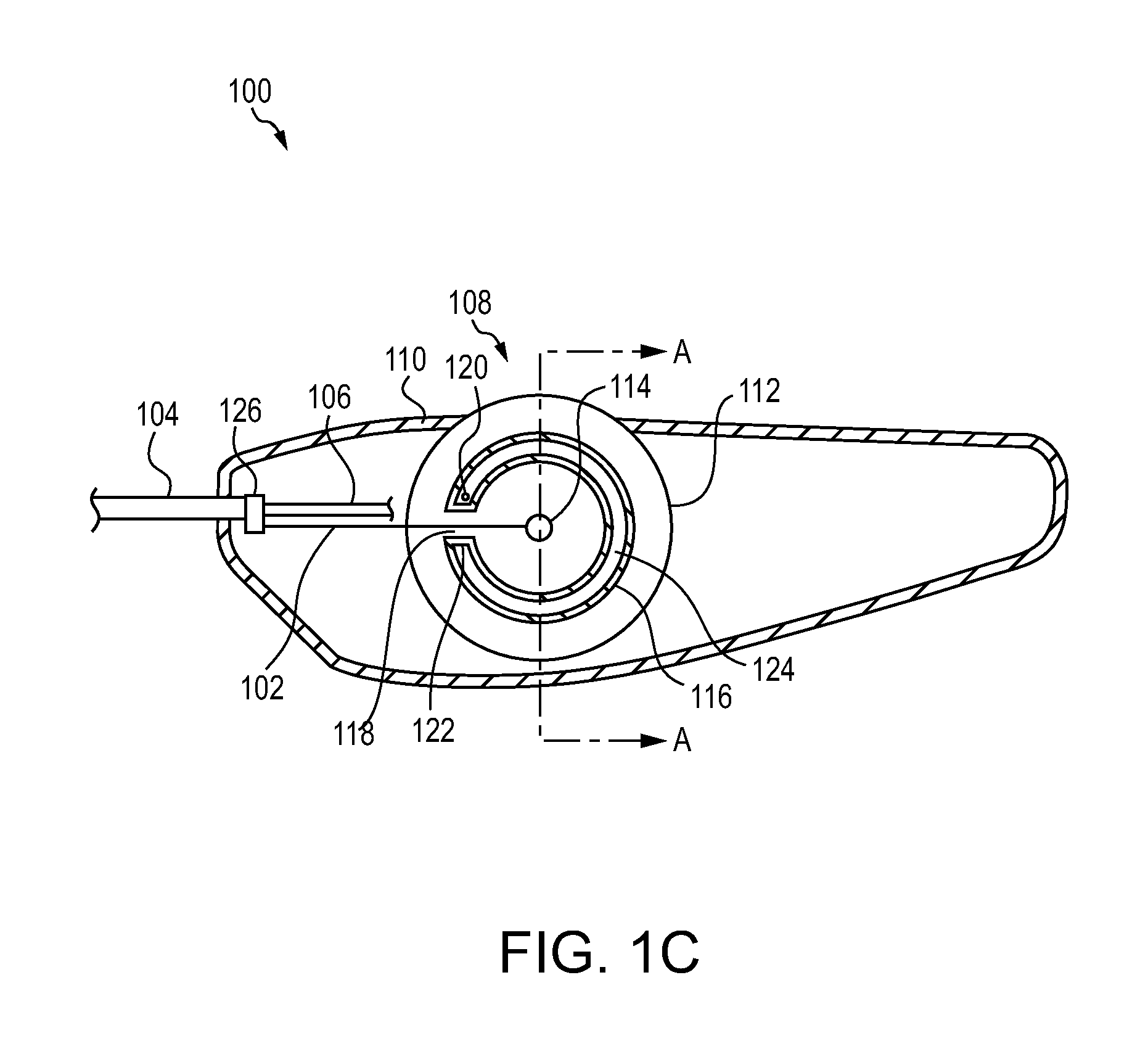
[0024]Various embodiments are described below with reference to the drawings. The relationship and functioning of the various elements of the embodiments may better be understood by reference to the following detailed description. However, embodiments are not limited to those illustrated in the drawings. It should be understood that the drawings are not necessarily to scale, and in certain instances details may have been omitted that are not necessary for an understanding of embodiments disclosed herein, such as—for example—conventional fabrication and assembly. The invention is defined by the claims, may be embodied in many different forms, and should not be construed as limited to the embodiments set forth herein; rather, these embodiments are provided so that this disclosure will be thorough and complete, and will fully convey enabling disclosure to those skilled in the art. As used in this specification and the claims, the singular forms “a,”“an,” and “the” include plural refere...


PUM


Abstract

A wire collection device for a stent delivery system includes a plurality of nested wire collection drums with a first drum concentric in a second drum. A thumbwheel coupled to the first drum can rotate to actuate rotation of the first drum to collect the retraction wire around the diameter of the first drum. A catching mechanism can rotate about the first drum to engage a catch portion of the second drum and actuate rotation of the second drum to collect the retraction wire around the outer diameter of the second drum. This increases the collection diameter of the retraction wire to provide a mechanical advantage for sheath retraction.

Description

CROSS-REFERENCE TO RELATED APPLICATIONS[0001]This application is a non-provisional application which claims priority to U.S. provisional application Ser. No. 61 / 867,926, filed Aug. 20, 2013, which is incorporated by reference herein in its entirety.TECHNICAL FIELD[0002]Embodiments disclosed in the present application relate generally to wire collection devices for providing a mechanical advantage in a stent delivery system.BACKGROUND[0003]Current delivery systems for self-expanding stents generally employ “pin and pull” systems that include an inner catheter extending through an outer sheath. Typically, the stent is placed inside the outer sheath and held in a compressed position by the outer sheath as the outer sheath and inner catheter are inserted into a patient's body vessel. To deploy the stent, the user retracts, or pulls, the outer sheath using one hand while the other hand holds the inner catheter stationary to maintain position of the stent as the outer sheath is retracted,...

Claims


Application Information

Patent Timeline
Patent Type & Authority Applications(United States)
IPC IPC(8): A61F2/966
CPCA61F2/966A61F2/9517A61F2002/9665A61F2/95
Inventor COSTELLO, KIERAN
Owner COOK MEDICAL TECH LLC
Why Eureka
Try Eureka