Arrangement of an intercooler in an intake pipe

Inactive Publication Date: 2015-03-05
BEHR GMBH & CO KG
View PDF15 Cites 5 Cited by
  • Summary
  • Abstract
  • Description
  • Claims
  • Application Information

AI Technical Summary

Benefits of technology

[0019]It is also advantageous when the housing part can be connected to the intake pipe. The second openin

Problems solved by technology

One disadvantage of the prior art is that, owing to this manner of installation, vibrations at the intake pipe and stresses, which can be produced owing to tolerances which are not 100% between the flange of the charge air cooler and the intake pipe, are transmitted directly to the charge air cooler.
This can lead to considerable problems in respect of the posi

Method used


Image

  • Arrangement of an intercooler in an intake pipe
  • Arrangement of an intercooler in an intake pipe
  • Arrangement of an intercooler in an intake pipe

Examples


Embodiment Construction

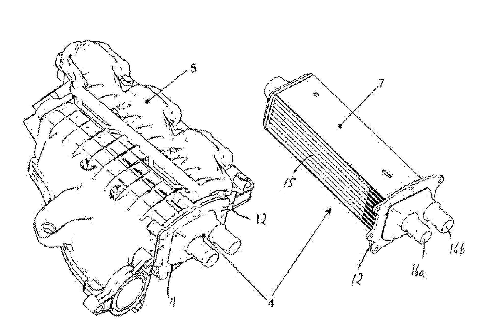
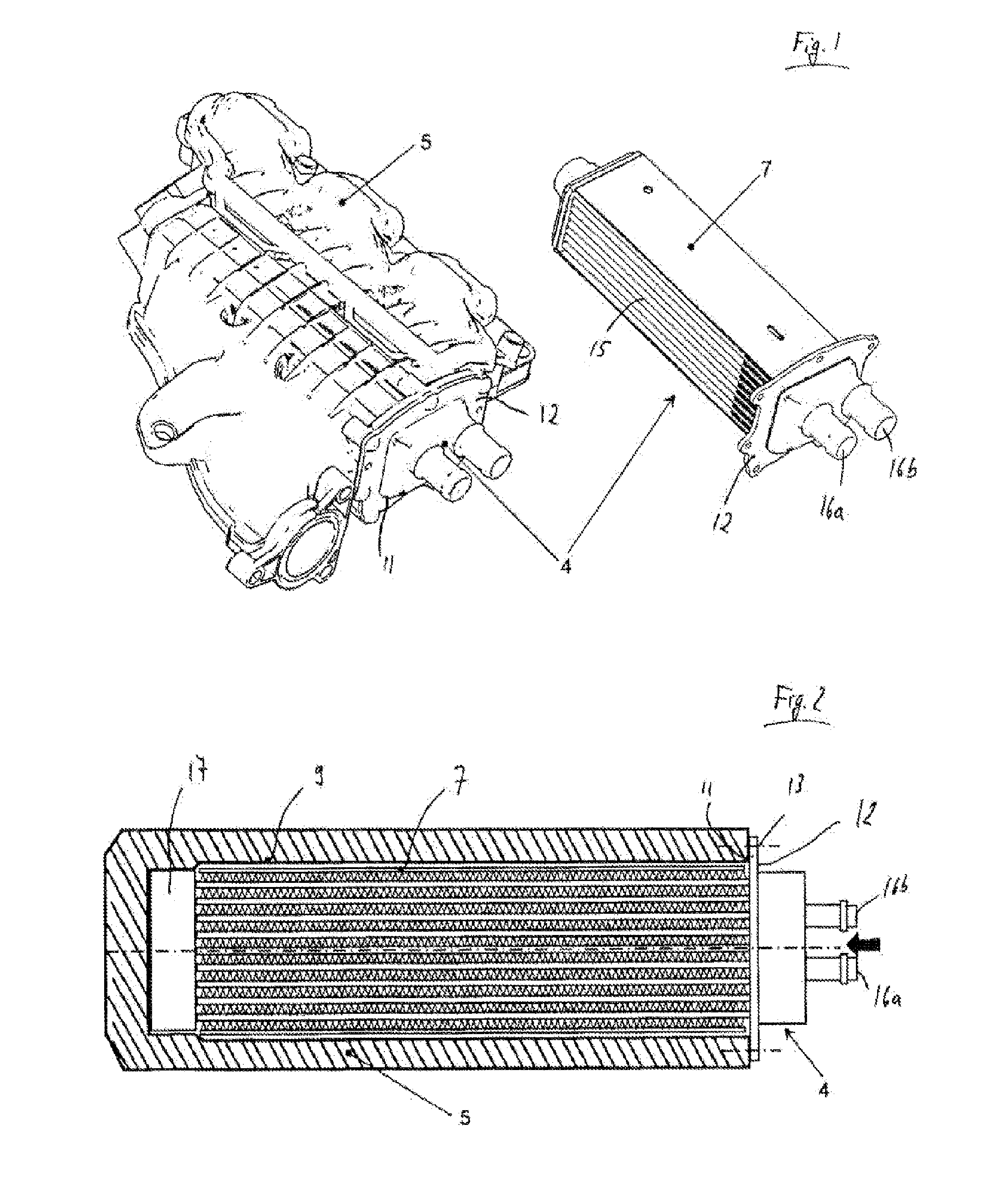
[0026]FIG. 1 shows, in the left-hand half of the image, a perspective outside view of an intake pipe 5. Said intake pipe 5 serves to supply air to an internal combustion engine, not shown in the figure. Compression of the intake air in a turbocharger or a compressor heats the air. As a result, the density of the air is reduced, and this would lead to relatively poor filling of the combustion spaces in the internal combustion engine. A charge air cooler 4 is installed in the intake pipe 5 for the purpose of cooling the air which is supplied to an internal combustion engine via the intake pipe 5, and therefore of increasing the density of the intake air.

[0027]The more precise internal design of the intake pipe 5 is not described in further detail at this point since it is not essential to the invention. The installation principle of the charge air cooler 4 in the intake pipe 5 is clear from the drawing on the left-hand side of FIG. 1.

[0028]The right-hand half of FIG. 1 shows the charg...


PUM


Abstract

Arrangement of an intercooler in an intake pipe, wherein the intercooler has a cooler block through which charge air can flow and a first opening through the intake pipe, through which the intercooler can be inserted into the intake pipe, wherein the intake pipe has a second opening, which is arranged substantially opposite the first opening and can be closed by means of a housing part.

Description

TECHNICAL FIELD[0001]The invention relates to an arrangement of a charge air cooler in an intake pipe, wherein the charge air cooler has a cooler block through which charge air can flow and through the intake pipe has a first opening, it being possible for the charge air cooler to be inserted into the intake pipe through said opening.PRIOR ART[0002]Charge air coolers are used for cooling the charge air in charged motors. This is necessary since the intake air is heated owing to the compression in a turbocharger. This leads to a reduction in the density of the intake air. This effectively leads to a lower oxygen content in the combustion space charge.[0003]In contrast to compression, cooling by the charge air cooler causes an increase in the density, as a result of which intake air with a high density is supplied to the combustion space of the internal combustion engine. The content of oxygen which is required for the combustion is particularly high in air with a high density.[0004]I...

Claims


Application Information

Patent Timeline
IPC IPC(8): F02B29/04
CPCF02B29/045F02B29/0406F02B29/0462F02B29/0475Y02T10/12
Inventor FEHRENBACH, MATTHIASHELMS, WERNERKOLBLIN, RUDIGERSAUMWEBER, CHRISTIAN
Owner BEHR GMBH & CO KG
Why Eureka
Try Eureka