Exercise equipment frame having sectional structural members

Active Publication Date: 2015-03-05
POWERBLOCK HLDG
View PDF13 Cites 62 Cited by
  • Summary
  • Abstract
  • Description
  • Claims
  • Application Information

AI Technical Summary

Benefits of technology

[0008]One aspect of this invention relates to an exercise equipment frame. The frame comprises a pair of spaced, parallel, vertically extending uprights that are fixedly secured to one another by at least one cross member. Each upright comprises a hollow tube. Each upright has at least a pair of opposite sides having matching arrays of vertically spaced apart holes carried thereon. The holes provide a series of a plurality of vertically spaced apart hole pairs on each upright with each hole pair comprising a first hole on one side of the upright and a second hole on the opposite side of the upright with the first and second holes of the hole pair being at the same vertical elevation along the upright. A pair of elongated horizontal attachment members pass through vertically corresponding hole pairs on the pair of uprights. Each upright is formed from at least two separable sections that separate from one another at some vertical location between upper and lower ends of the series of hole pairs on the upright. One of the two separable sections has a reduced size end that is telescopically interfit into one end of the other section to couple the two sections together. The reduced size end of the one section has hole pairs therein that will align with and form continuations of the hole pairs in the one end of the other section when the telescopically interfitting connection between the two sections is fully made. In addition, the reduced size end of the one section and the one end of the other section will have an interference fit therebetween when the sections are telescopically interfit with one another which is sufficiently tight such that the sections can be telescopically interfit with one another only by using a force that is greater than the force a user can exert using hand pressure to push the sections together.

Problems solved by technology

In addition, the reduced size end of the one section and the one end of the other section will have an interference fit therebetween when the sections are telescopically interfit with one another which is sufficiently tight such that the sections can be telescopically interfit with one another only by using a force that is greater than the force a user can exert using hand pressure to push the sections together.

Method used


Image

  • Exercise equipment frame having sectional structural members
  • Exercise equipment frame having sectional structural members
  • Exercise equipment frame having sectional structural members

Examples


Embodiment Construction

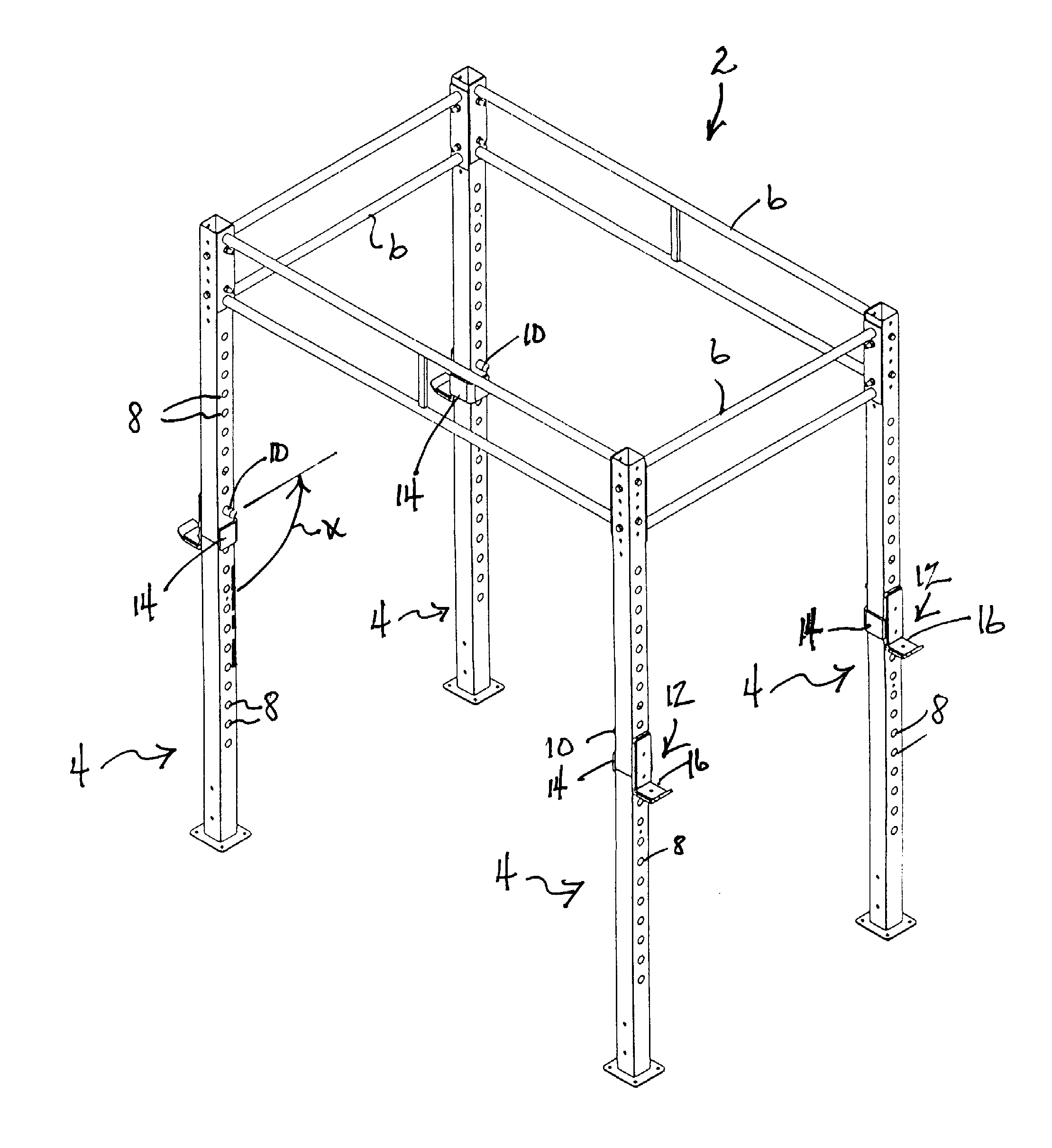
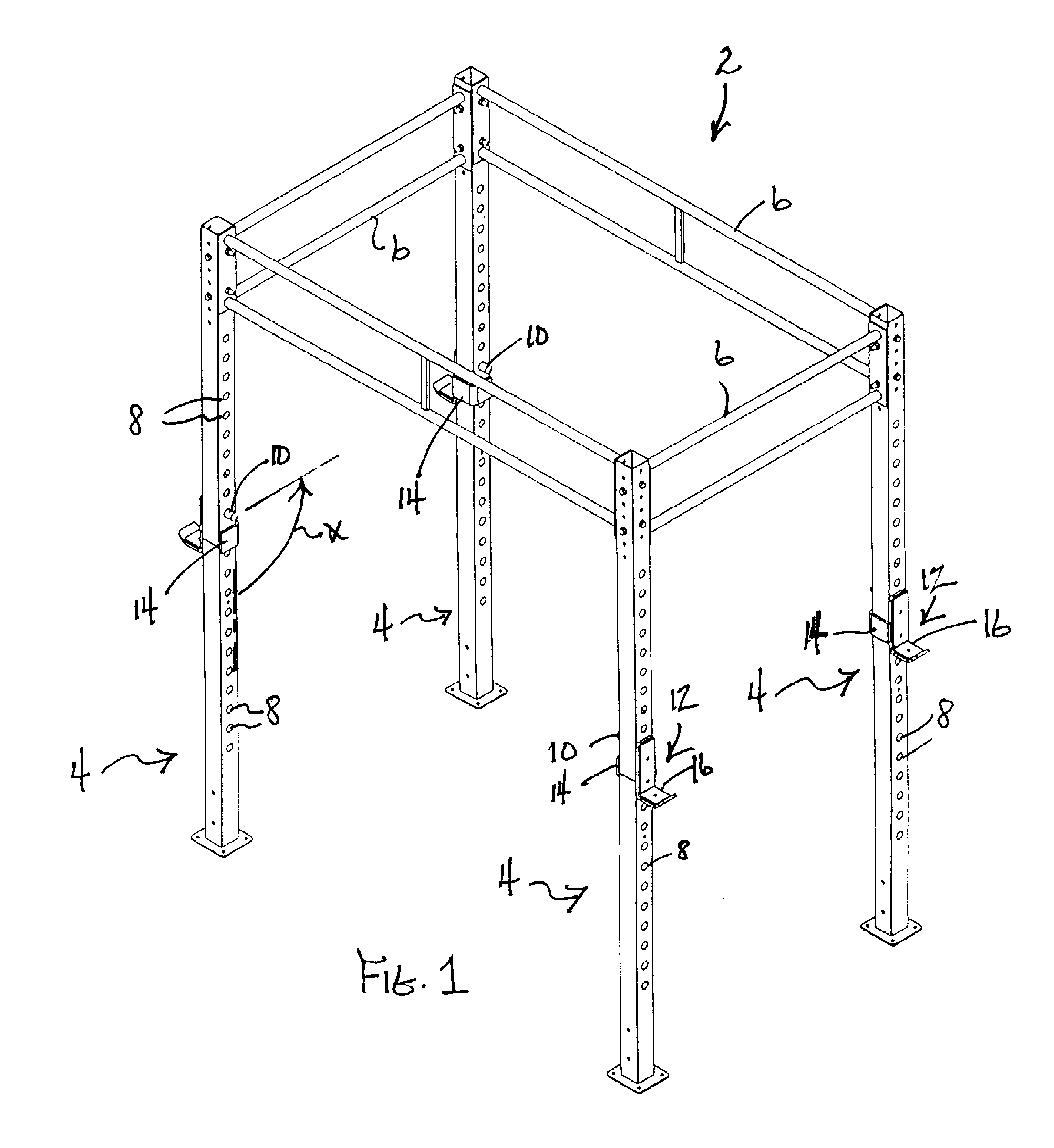
[0021]Referring first to FIG. 1, a weight lifting frame according to one embodiment of this invention is generally illustrated as 2. Frame 2 depicted in FIG. 1 is a free standing frame, often referred to as a power cage, having four vertical uprights 4. Uprights 4 are positioned at the four corners of the cage structure. Uprights 4 are rigidly connected together at the top thereof by a plurality of laterally and longitudinally extending cross members 6 that are bolted to the upper ends of uprights 4 to form frame 2.

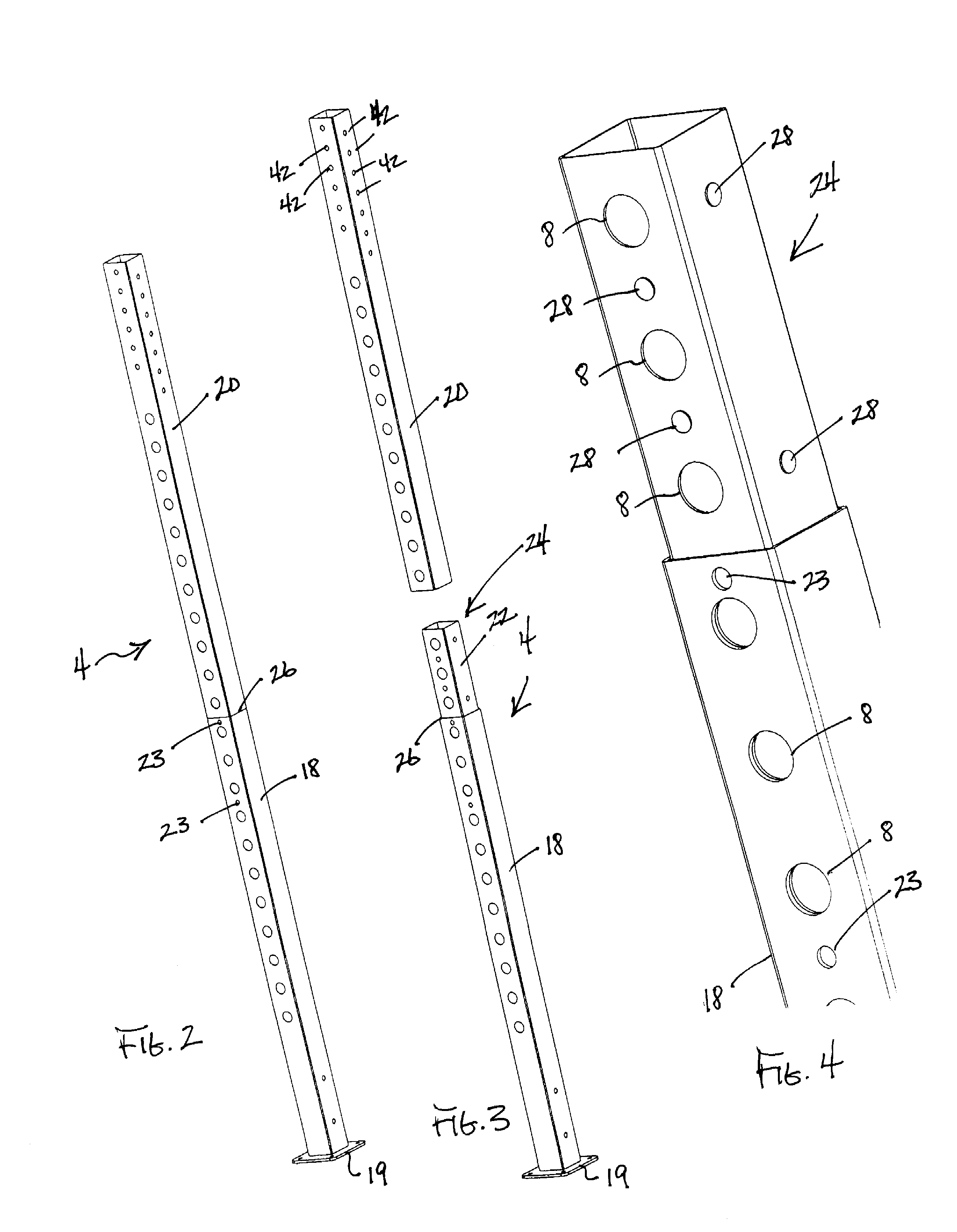
[0022]As also shown in FIG. 1, each upright 4 carries on two opposite sides thereof a plurality of large holes 8 that are vertically spread apart along a substantial portion of the length of upright 4 at substantially equal intervals. Large holes 8 permit the mounting pin 10 of a bar support 12, known as a J-cup, to pass through a first selected hole 8 on one side of upright 4, through the open interior of upright 4 since upright 4 is formed as a hollow tube, and then out...


PUM


Abstract

An exercise equipment frame, such as a power cage, is formed from uprights that comprise at least two sections that are telescopically interfit with one another. The sections have an interference fit between them when the telescopic interconnection is made that is tight enough to require the use of a tool that enables leverage greater than that achievable by the hand pressure of a user. The sections may be of substantially equal length to one another when forming the main uprights of the frame to allow packaging of the sections when disassembled in a carton of more regular dimensions. The sections may also be unequal length to allow coupling of a frame extension to the top of a completed power cage type frame.

Description

TECHNICAL FIELD[0001]This invention relates to the exercise equipment field and, more particularly, to a frame for holding or racking weights, such as barbells, used in weight lifting exercises or for supporting other exercise devices, such as chin up bars, thereon.BACKGROUND OF THE INVENTION[0002]Weight lifting exercises are often performed with a barbell. A barbell includes an elongated grip bar that is long enough for a user to grip the central portion of the grip bar with both hands. The bar when so gripped is also long enough to extend horizontally and laterally outside of or beyond the shoulders of the user, i.e. the bar has a length that is substantially longer than the shoulder width of the user. A selected number and / or size of weights can be loaded onto each of the ends of the bar such that a desired total exercise mass is provided by the barbell. The user may then lift and lower the barbell to perform different types of exercises, such as a bench press, a squat, etc.[0003...

Claims


Application Information

Patent Timeline
Patent Type & Authority Applications(United States)
IPC IPC(8): A63B21/00
CPCA63B21/00047A63B17/04A63B21/078A63B23/1218A63B2225/093F16B7/105
Inventor TOWLEY, III, CARL K.OLSON, GREGORY S.
Owner POWERBLOCK HLDG
Why Eureka
Try Eureka