Fuselage-mounted landing gear assembly for use with a low wing aircraft

a low-wing aircraft and fuselage-mounted technology, applied in the field of aircraft, can solve the problems of significant increase in the overall area of the wing root, at least one of the above goals may be at risk, difficult to optimize,

Inactive Publication Date: 2015-03-12
THE BOEING CO
View PDF17 Cites 28 Cited by
  • Summary
  • Abstract
  • Description
  • Claims
  • Application Information

AI Technical Summary

Benefits of technology

[0008]In one aspect, a landing gear assembly for use with a low wing aircraft is provided. The landing gear assembly comprises a truck assembly and a shock strut coupled to and configured to support the truck assembly. The landing gear assembly further comprises a retraction assembly coupled to the shock strut and to the truck assembly. The retraction assembly is configured to selectively move the landing gear assembly between a retracted position and a deployed position. The retraction assembly comprises a main trunnion brace having a first end and a second end, wherein the first end is coupled to a fuselage of the aircraft at a first pivot point and the second end is coupled to the truck assembly. The main trunnion brace is configured to position the truck assembly, the shock strut, and the retraction assembly fully within the fuselag

Problems solved by technology

On any low wing or other aircraft in which the main landing gear is stored or attached to a wing of the aircraft, at least one of the above goals may be at risk and may be difficult to optimize.
In the case of wing-mounted landing gear configurations, for example, the wing efficiency goal may be compromised.
However, wing-mounted landing gear assemblies generally require a large physical footprint in the inboard area of the wing for storage when retracted, which significantly increases the overall area of the wing root.
The increased area of the wing root increases the overall weight of the aircraft and may decrease the potential efficiency of the wing.
In addition, fuselage mounted landing gear (FMLG) designs, common on high and middle wing aircraft, may be heavy and create significant drag relative to a low wing aircraft.
However, the increased gear components increase the weight and frontal area of the wing

Method used


Image

  • Fuselage-mounted landing gear assembly for use with a low wing aircraft
  • Fuselage-mounted landing gear assembly for use with a low wing aircraft
  • Fuselage-mounted landing gear assembly for use with a low wing aircraft

Examples


Embodiment Construction

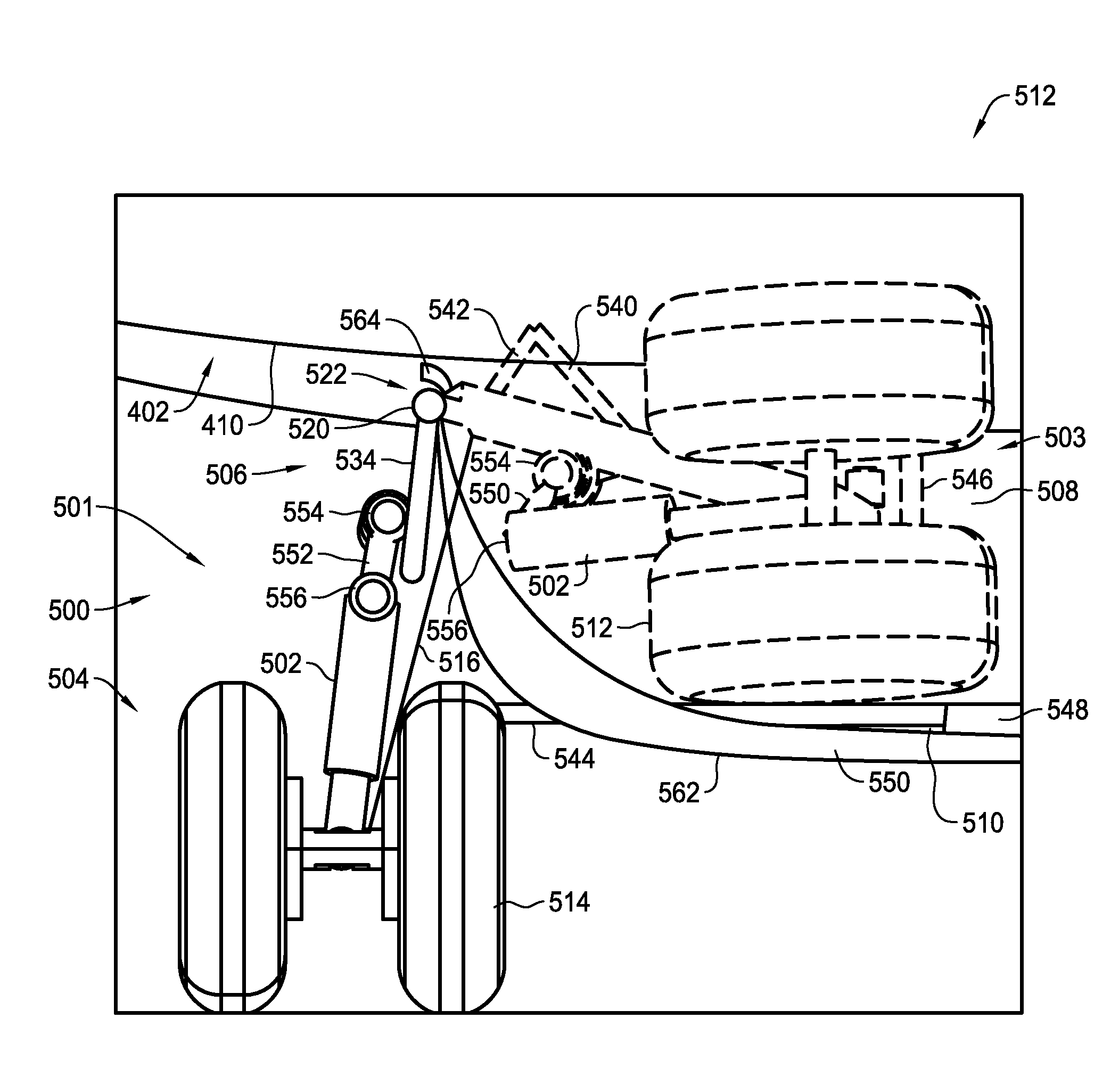
[0020]The implementations described herein relate to assemblies and methods that facilitate improving the efficiency of an aircraft wing by reducing the interference between the wing, landing gear doors, and landing gear assembly of a low wing aircraft. In an exemplary implementation, the aircraft includes at least one wing that includes a trailing edge flap that is selectively moveable between a stowed position and an extended position. The aircraft also includes a fuselage that includes a first gear door on a side of the fuselage and a second gear door on a bottom of the fuselage. The first gear door defines a first gear door envelope between a closed position and an open position. A landing gear assembly is coupled to the fuselage and is selectively moveable between a retracted position and a deployed position. The trailing edge flap may be extended simultaneously with, before, or after deployment of the landing gear assembly and opening of the first gear door, such that the trai...


PUM


Abstract

An aircraft comprises at least one wing comprising a trailing edge flap that is selectively moveable between a stowed position and an extended position. The aircraft also includes a fuselage comprising a first gear door on a side of the fuselage and a second gear door on a bottom of the fuselage. The first gear door is moveable in a gear door envelope between a closed position and an open position. The wing is coupled to the fuselage in a low-wing configuration. A landing gear assembly is coupled to the fuselage and is selectively moveable between a retracted position and a deployed position. The trailing edge flap may be extended simultaneously with, before, or after deployment of the landing gear assembly and opening of the first gear door.

Description

BACKGROUND[0001]The field of the present disclosure relates generally to an aircraft, and, more specifically, to fuselage-mounted landing gear for use with a low wing aircraft.[0002]An effective landing gear design for an aircraft should provide an optimum combination of sufficient overall functional strength, a geometric arrangement for adequate ground maneuvering and landing stability, a lowest possible weight, and a highest possible wing efficiency when retracted. On any low wing or other aircraft in which the main landing gear is stored or attached to a wing of the aircraft, at least one of the above goals may be at risk and may be difficult to optimize. In the case of wing-mounted landing gear configurations, for example, the wing efficiency goal may be compromised.[0003]To enhance stability and to prevent wallowing during ground maneuvers, an aircraft's main landing gear must be placed sufficiently outboard of the side of the body of the aircraft. On low wing aircraft this is ...

Claims


Application Information

Patent Timeline
IPC IPC(8): B64C25/12
CPCB64C25/12B64C2025/125
Inventor BROWN, STEPHEN T.DRAKE, MICHAEL LANEHOLTORF, CHRISTOPHER R.COTTET, JUSTIN
Owner THE BOEING CO
Why Eureka
Try Eureka